
Test tube capping device

A test tube and cap body technology, which is applied in the field of test tube capping devices, can solve the problems such as the need for regular cleaning of the head, the inability to use capping equipment, and the poor packaging, so as to achieve simple and convenient installation and cap opening, compact structure and safety. , the effect of simple structure design

Pending Publication Date: 2022-07-29
YANTAI ADEKANG BIOTECHNOLOGY CO LTD
View PDF0 Cites 0 Cited by
  • Summary
  • Abstract
  • Description
  • Claims
  • Application Information

AI Technical Summary

Problems solved by technology

At present, the automatic medical inspection assembly line uses aluminum foil hot-melt to package vacuum blood collection tubes, which may not be tightly packaged, and can only be packaged with plastic materials, not glass vacuum blood collection tubes. Special film removal equipment is required for re-examination, and the original ones cannot be used. The uncapping equipment increases the number of equipment and space occupation
In addition, the existing medical inspection automatic assembly line sealing machine adopts rack lifting, connecting rod cylinder rotation, electric heating of aluminum film on the head, high temperature melting blood collection tube and aluminum film welding to achieve packaging, which has complex structure, difficult processing and high cost. , the head needs to be cleaned regularly, and the mechanical failure rate is high

Method used


Image

  • Test tube capping device
  • Test tube capping device
  • Test tube capping device

Examples


Embodiment Construction

[0033] The technical solutions in the embodiments of the present invention will be clearly and completely described below with reference to the accompanying drawings in the embodiments of the present invention. Obviously, the described embodiments are only a part of the embodiments of the present invention, but not all of the embodiments. Based on the embodiments of the present invention, all other embodiments obtained by those of ordinary skill in the art without creative efforts shall fall within the protection scope of the present invention.

[0034] In the description of the present invention, it should be understood that the terms "center", "longitudinal", "lateral", "length", "width", "thickness", "upper", "lower", "front", " The orientation or positional relationship indicated by "rear", "left", "right", "vertical", "horizontal", "top", "bottom", "inside", "outside", etc. is based on the orientation shown in the drawings Or the positional relationship is only for the co...


PUM


Abstract

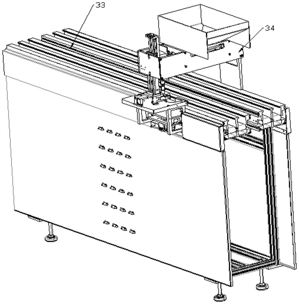
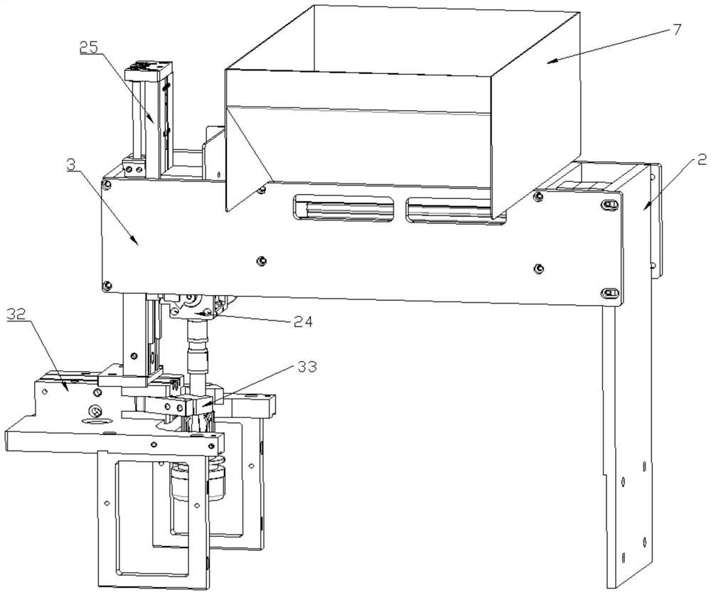
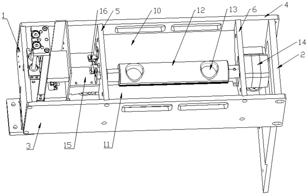
The invention relates to a test tube capping device which comprises a cap body conveying mechanism, the cap body conveying mechanism comprises a hopper and a conveying belt arranged below the hopper, and the width of the conveying belt is matched with the diameter of a cap body; the cover body steering mechanism comprises a steering shaft, the steering shaft is provided with a cover body penetrating part, the shape of the cover body penetrating part is matched with that of the cover body, the cover body penetrating part is connected with the conveying belt, and the steering shaft can rotate and is used for adjusting the direction of the cover body; and the cover body pressing mechanism comprises a pressing block and a driving part connected to the pressing block, the driving part is used for driving the pressing block to do reciprocating motion in the direction close to or away from the test tube, and the pressing block is connected to the steering shaft. According to the test tube capping device, ordered transfer of the cap bodies can be achieved, the transfer speed of the cap bodies can be controlled, it is guaranteed that the cap bodies cannot be stacked in the transfer process, the structure is simple, and the alignment accuracy of various types of test tubes and the cap bodies can be improved.

Description

technical field [0001] The invention relates to the technical field of medical equipment, in particular to a test tube capping device. Background technique [0002] At present, the automation of medical inspection is realized through the inspection assembly line. The sample container to be tested is a vacuum blood collection tube. During the test, the vacuum blood collection tube needs to be opened for automatic sampling inspection in the next step. The samples will be stored for a certain period of time for subsequent re-examination. In order to ensure the validity of the samples, the vacuum blood collection tubes need to be sealed and stored. At present, the medical inspection automation assembly line uses aluminum foil hot-melt to package the vacuum blood collection tube, which may not be tightly packaged, and can only be packaged with plastic material, not glass material. The opening of the device increases the number of devices and space occupation. In addition, the e...

Claims


Application Information

Patent Timeline
Patent Type & Authority Applications(China)
IPC IPC(8): B67B3/00B67B3/06
CPCB67B3/00B67B3/06
Inventor 高海荣孟德明胡桂华王云赵鹏宇乔永强王晓凤
Owner YANTAI ADEKANG BIOTECHNOLOGY CO LTD
Learn More