
Accelerator pedal arm supporting seat bottom face finish machining machine tool

A technology of accelerator pedal and support seat

Active Publication Date: 2022-07-29
WUHU HENGHAO MACHINERY MFG
View PDF9 Cites 0 Cited by
  • Summary
  • Abstract
  • Description
  • Claims
  • Application Information

AI Technical Summary

Problems solved by technology

[0004] In order to overcome the above-mentioned defects of clamping the bottom of the accelerator pedal arm support seat and not taking into account the processing of its bottom surface, the present invention proposes a finishing machine tool for the bottom surface of the accelerator pedal arm support seat

Method used


Image

  • Accelerator pedal arm supporting seat bottom face finish machining machine tool
  • Accelerator pedal arm supporting seat bottom face finish machining machine tool
  • Accelerator pedal arm supporting seat bottom face finish machining machine tool

Examples


Embodiment 1

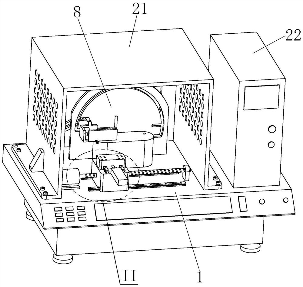
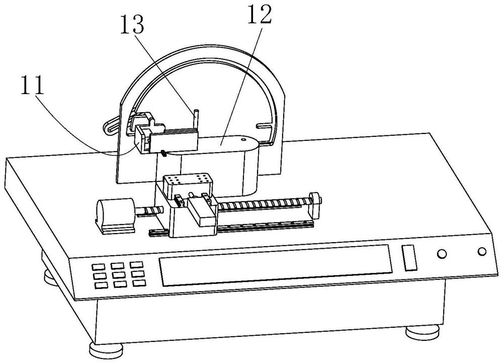
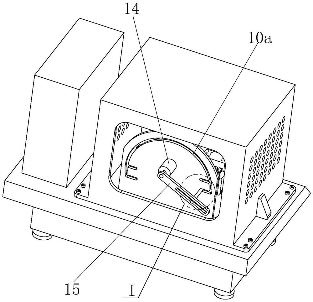
[0035] like Figure 1 to Figure 7 As shown in the figure, the bottom surface of the accelerator pedal arm support base is a finishing machine tool, and a host table 1 is provided. The upper and front part of the host table 1 is installed with a two-degree automatic moving mechanism, and the two-automatic moving mechanism is connected with the main mounting seat 2; The rear part is respectively provided with a positioning assembly, a clamping assembly and a clamp-changing moving assembly; the clamping-changing moving assembly includes a rail placement plate 8 installed on the main table 1, and the rail placement plate 8 is slidably fitted with I-type connecting rods 9 and II-type connecting rods respectively. The connecting rod 10; the clamping assembly includes a three-sided load frame 11 which is connected to the I-type connecting rod 9 and the II-type connecting rod 10 by welding.

[0036] like figure 1 As shown, an outer cover 21 and an electric control box 22 are respecti...

Embodiment 2

[0047] The present invention also further proposes a working method, specifically:

[0048] In the initial state, the I-type connecting rod 9 and the II-type connecting rod 10 are respectively located at the right limit positions of the two horizontal grooves 10b on the left side.

[0049] Before use, the external finishing equipment is manually installed on the main mounting seat 2 .

[0050] The specific use steps are as follows:

[0051] Step one, as Figure 8 The illustrated accelerator pedal arm support is placed on the pad 12 with the bottom facing forward, and the shaft hole on the workpiece is matched with the positioning pin 13, and the left end of the bottom of the workpiece is abutted with the fixed clamping plate 18.

[0052] Step 2. The air cylinder 16 pulls the movable clamping plate 19 back, and clamps the bottom left end of the workpiece. The clamped state is as follows: Figure 9 shown.

[0053] Step 3: Process the right half of the bottom surface of the w...


PUM


Abstract

The invention relates to an accelerator pedal arm supporting seat bottom face finish machining machine tool which is provided with a main machine table, and a two-degree-of-freedom moving mechanism is installed on the front portion of the main machine table and connected with a main installation seat. A positioning assembly, a clamping assembly and a clamp changing moving assembly are arranged on the rear portion of the main machine table. The clamp changing moving assembly comprises a rail placing plate installed on the main machine table, and the rail placing plate is in sliding fit with an I-type connecting rod and an II-type connecting rod. The clamping assembly comprises a three-face load frame connected with the I-shaped connecting rod and the II-shaped connecting rod in a welded mode. Positioning and clamping are convenient, a workpiece can be prevented from loosening, the machining precision is higher, manual adjustment and automatic machining control can be facilitated, and finish machining operation is more convenient and faster; the technical problem that automatic machining of the whole bottom face is difficult to consider during bottom clamping is solved, a large amount of equipment cost is saved, the clamping time is shortened, and the machining efficiency is relatively improved.

Description

technical field [0001] The invention relates to the technical field of production and processing of auto parts, in particular to a machine tool for finishing the bottom surface of an accelerator pedal arm support seat. Background technique [0002] The accelerator pedal arm support seat, also known as the accelerator bracket, is an important carrier for loading the accelerator wall and other related components in the accelerator pedal assembly parts. The bottom surface is polished, ground and other related finishing processes. [0003] In the traditional machining mode, the clamps are clamped by the two sides of the space, even if the direction of the clamping force is not in the same direction as the direction of the machining force, it is easy to cause loosening during machining, resulting in scrapped workpiece machining. . Although there have been attempts to clamp the bottom, this will result in a part of the bottom surface being machined by the clamping cover. SUMMA...

Claims


Application Information

Patent Timeline
Patent Type & Authority Applications(China)
IPC IPC(8): B24B19/00B24B27/02B24B41/06B24B47/06B24B55/00
CPCB24B19/00B24B27/02B24B41/06B24B47/06B24B55/00
Inventor 袁道华袁昊陶代保陶代华
Owner WUHU HENGHAO MACHINERY MFG
Learn More