
Full-automatic exposure machine

An exposure machine and fully automatic technology, applied in the field of exposure machines, can solve problems such as the large space occupied by the automation system, the compression of the user's production space, and the inability to complete the production process, so as to improve the overall transmission efficiency, reduce the space for activities, The effect of optimizing headspace

Pending Publication Date: 2022-07-26
SUZHOU YUANZHUO OPTOELECTRONICS TECH CO LTD
View PDF0 Cites 0 Cited by
  • Summary
  • Abstract
  • Description
  • Claims
  • Application Information

AI Technical Summary

Problems solved by technology

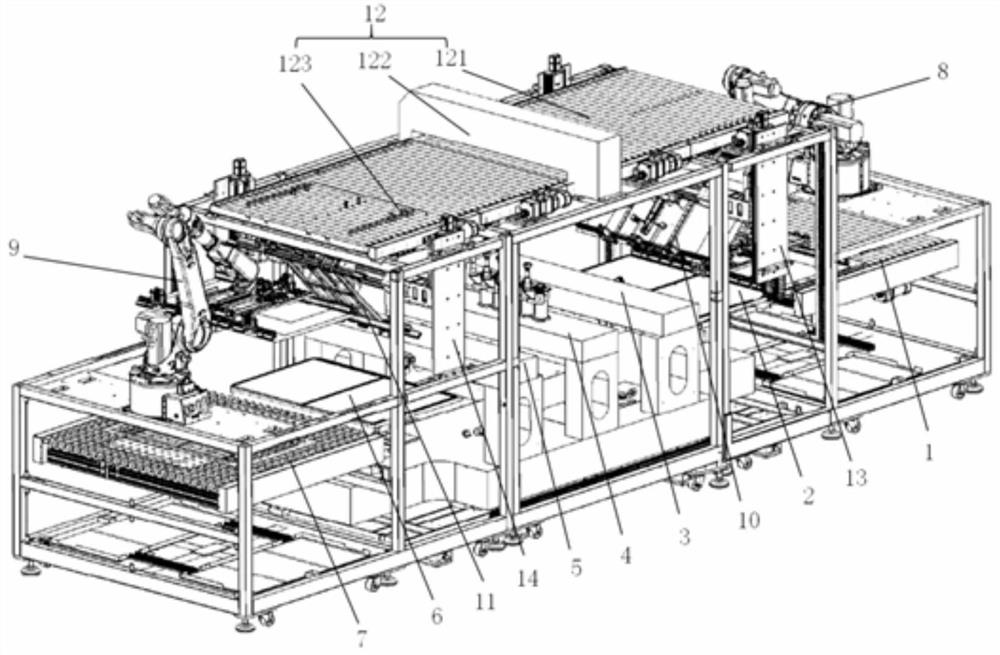
Although this double-sided exposure method realizes the automation of double-sided exposure, it requires two independent exposure machines, which means that two alignment mechanisms and two exposure systems are required for alignment and exposure respectively. The entire automation system Occupies a lot of space, especially for venues that need to occupy a large area
[0003] In addition, the cost of using two exposure machines, auxiliary flippers and corresponding manipulators is very high, and the movement trajectory of traditional manipulators will also lead to a large space occupation of the overall equipment. In addition to the aforementioned footprint, in the height direction The space occupied by the website may further compress the limited production space of the user
However, the excessive range of movement of traditional manipulators will also lead to a decrease in production efficiency and cannot optimize the production process.

Method used


Image

  • Full-automatic exposure machine
  • Full-automatic exposure machine
  • Full-automatic exposure machine

Examples


Embodiment Construction

[0058] In order to make the technical solutions of the present invention clearer, the embodiments of the present invention will be described below with reference to the accompanying drawings. It should be understood that the specific descriptions of the embodiments are only used to teach those skilled in the art how to implement the present invention, rather than to exhaust all possible ways of the present invention, nor to limit the specific implementation scope of the present invention. Based on the embodiments of the present invention, all other embodiments obtained by those of ordinary skill in the art without creative work shall fall within the protection scope of the present invention.

[0059] It should be noted that the terms "center", "upper", "lower", "front", "rear", "left", "right", "horizontal", "top", "bottom", "inside", The orientation or positional relationship indicated by "outside", "vertical", "horizontal", "horizontal", "longitudinal", "vertical", etc. is b...


PUM


Abstract

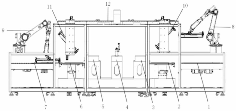
A full-automatic exposure machine comprises a first table top, a second table top, an exposure system, at least two grabbing manipulators and at least one temporary storage manipulator, the first table top and the second table top are located at the two ends of the exposure system and can move to the exposure system respectively, and the first table top and the second table top are both used for containing a substrate to be exposed; and at least one temporary storage manipulator grabs the base part from the first table top or the second table top, handover is carried out after the grabbing manipulator closest to the temporary storage manipulator is vacant, and then the grabbing manipulator transfers the base part to the next station. According to the full-automatic exposure machine disclosed by the invention, the transfer of the substrate is more efficient, the exposure capacity is higher, the structure of the whole machine system is compact, the occupied area and the occupied height space are obviously reduced, and particularly, the occupied area is obviously reduced.

Description

technical field [0001] The invention relates to the technical field of exposure machines, in particular to a fully automatic exposure machine. Background technique [0002] In order to adapt to the development of intelligent and miniaturized electronic products, the processing of electronic circuit boards is no longer limited to exposure processing on one side of the base member, but usually requires exposure processing of electronic circuits on both sides of the base member. However, at present, when double-sided processing is performed on the base piece, two exposure machines and a flipping machine are usually required. Specifically, a first exposing machine and a second exposing machine are set, and a flipping machine is set between the first exposing machine and the second exposing machine. Trigger. The first exposure machine includes a first alignment mechanism and a first exposure system, the second exposure machine includes a second alignment mechanism and a second e...

Claims


Application Information

Patent Timeline
Patent Type & Authority Applications(China)
IPC IPC(8): G03F7/20
CPCG03F7/70733G03F7/7075G03F7/70716
Inventor 章卫平钱志斌张雷
Owner SUZHOU YUANZHUO OPTOELECTRONICS TECH CO LTD
Learn More