


Quick Research
Generate reliable direction feasibility study reports for your R&D in just a few steps.

Technical Q&A
Discover and master advanced knowledge NOW. Basics, ideas, possibilities, all at once.

Find Solutions
As an expert in R&D theories, this can generate solutions to your technical problems instantly.

Evaluate Feasibility
Analyze your overall solution with one click, know your potential R&D risks in advance.

Monitor Landscape
Get weekly tech updates, stay abreast of the latest tech innovations and key insights.
Optical detection equipment
A technology of optical detection and equipment, which is applied in the direction of optical testing of flaws/defects, material analysis through optical means, and measurement devices, etc., which can solve the problems of cumbersome detection process, affecting the detection rate of wafer defects, and the inability to realize synchronous detection, etc. Achieve the effect of simplifying the inspection process, improving the defect detection rate and detection efficiency
- Summary
- Abstract
- Description
- Claims
- Application Information
AI Technical Summary
Problems solved by technology
Method used
Image

Examples
Embodiment 1
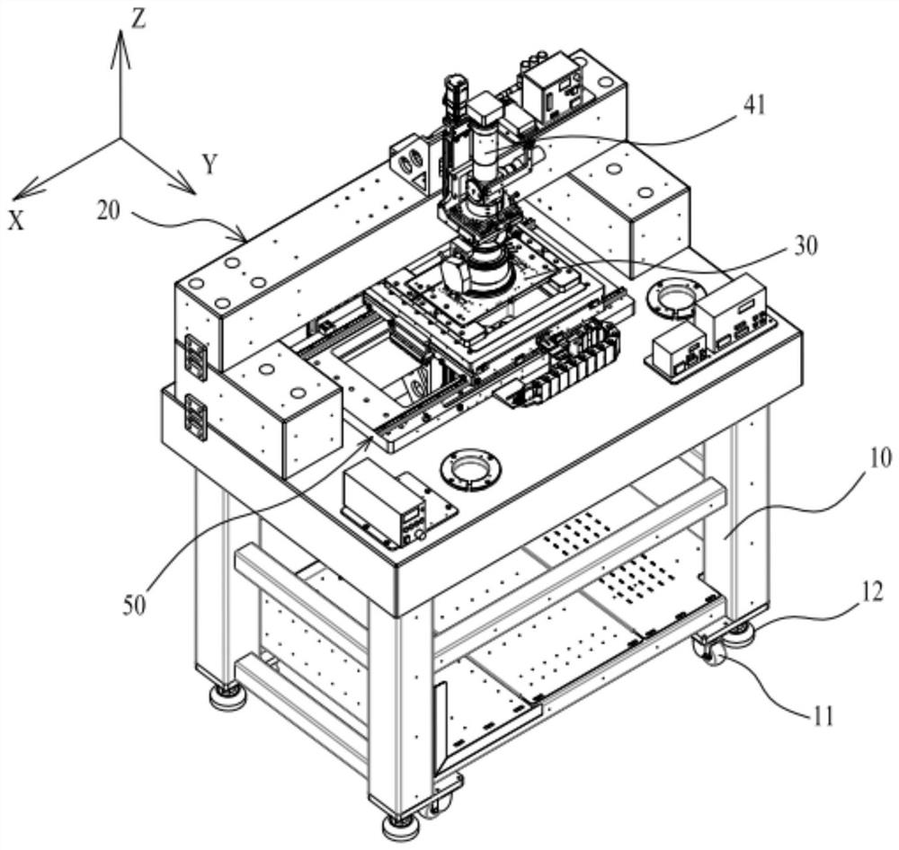
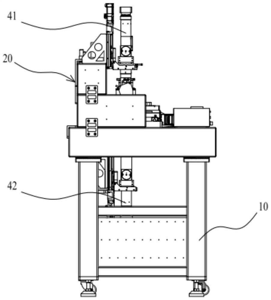
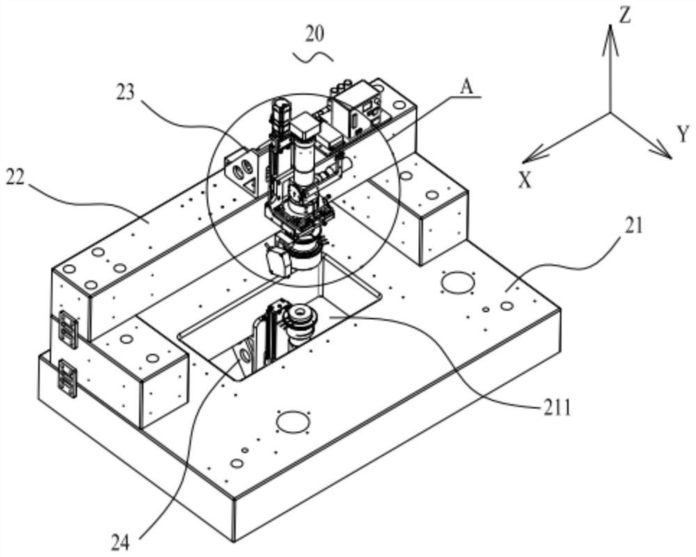
[0051] like figure 1 and figure 2 As shown, the optical inspection device provided in this embodiment is specifically used to detect defects on the wafer surface. The optical inspection equipment includes a bracket assembly 20, a stage 30 for carrying wafers to be inspected, a first main inspection lens 41, a second main inspection lens 42, a stage driving unit 50, and an imaging analysis unit (not shown) . In this embodiment, the first main inspection lens 41 and the second main inspection lens 42 are selected from 3 to 5 times lenses, and the resolution is 0.6 μm to 1.6 μm. Of course, it should be noted that the first main inspection lens 41 and the second main inspection lens 42 are not limited to 3-5x lenses, and their specific magnifications can be switched according to actual needs.
[0052] Specifically, the first main inspection lens 61 is mounted on the bracket assembly 20, and the camera end of the first main inspection lens 41 faces the side of the wafer to be i...
Embodiment 2
[0062] like Figure 7As shown, the optical inspection device provided in this embodiment is specifically used to detect defects on the wafer surface. The difference between the optical inspection device in this embodiment and the optical inspection device in the first embodiment is that a first re-inspection lens 61 and a second re-inspection lens 62 are added, and the carrier 30 drives the wafer to be inspected to move In order to enable the wafer to be inspected to enter the field of view of the first re-inspection lens 61 and the second re-inspection lens 62, the first re-inspection lens 61 and the second re-inspection lens 62 are respectively The imaging analysis unit is electrically connected, the first re-inspection lens 61 is used to obtain the first re-inspection image of the side of the wafer to be inspected facing away from the stage 30, and the second re-inspection lens 62 is used for A second re-inspection diagram of the wafer to be inspected attached to one side ...
Embodiment 3
[0067] like Figure 9 As shown, the optical inspection device provided in this embodiment is specifically used to detect defects on the wafer surface. The difference between the optical detection device in this embodiment and the optical detection device in the first embodiment is that a pre-inspection unit 70 is added. The pre-inspection unit 70 is electrically connected to the imaging analysis unit, and is used for acquiring a pre-inspection map of the wafer to be inspected. The purpose is to, as Figure 10 As shown, usually some dies on some wafers to be inspected need to be inspected (the gray area in the figure), while some dies do not need to be inspected (the light-colored area in the figure). The detected crystal grains are detected, the pre-checking unit 70 is added to mark the required crystal grains, and the marking is fed back to the imaging analysis unit, so that the imaging analysis unit only targets the crystal grains in the marked area. Defect detection is p...
PUM
 Abstract
Description
Claims
Application Information
 - R&D Engineer
- R&D Manager
- IP Professional
- Industry Leading Data Capabilities
- Powerful AI technology
- Patent DNA Extraction
Browse by: Latest US Patents, China's latest patents, Technical Efficacy Thesaurus, Application Domain, Technology Topic, Popular Technical Reports.
© 2024 PatSnap. All rights reserved.Legal|Privacy policy|Modern Slavery Act Transparency Statement|Sitemap|About US| Contact US: help@patsnap.com