
Centrifugal clutch

A centrifugal clutch and ring technology, applied in the field of clutches, can solve the problems affecting the friction coefficient of the friction plate, wear of the clutch elements, inconvenient operation and use, etc., and achieve the effects of large transmission torque, improved service life and convenient installation.

Pending Publication Date: 2022-07-22
XIAMEN SOUTH SUPER MACHINERY CO LTD
View PDF0 Cites 0 Cited by
  • Summary
  • Abstract
  • Description
  • Claims
  • Application Information

AI Technical Summary

Problems solved by technology

Because the temperature is too high or the temperature is too low, the friction coefficient of the friction plate will be affected, and the friction plate will easily slip and generate heat when it comes into contact with water or oil, which will affect the clutch effect.
In particular, the friction plate clutch for high torque occasions needs to be particularly bulky, resulting in many limitations
In addition, the sprag-type one-way clutches on the market, frequent clutch operations lead to greater wear and tear on the clutch elements, and are prone to abnormal noise, which is extremely inconvenient to operate

Method used


Image

  • Centrifugal clutch
  • Centrifugal clutch
  • Centrifugal clutch

Examples


Embodiment

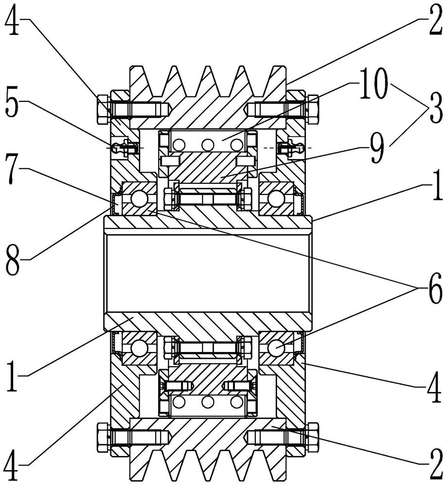
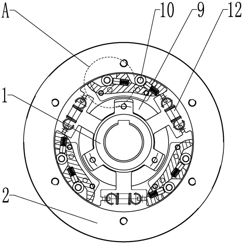
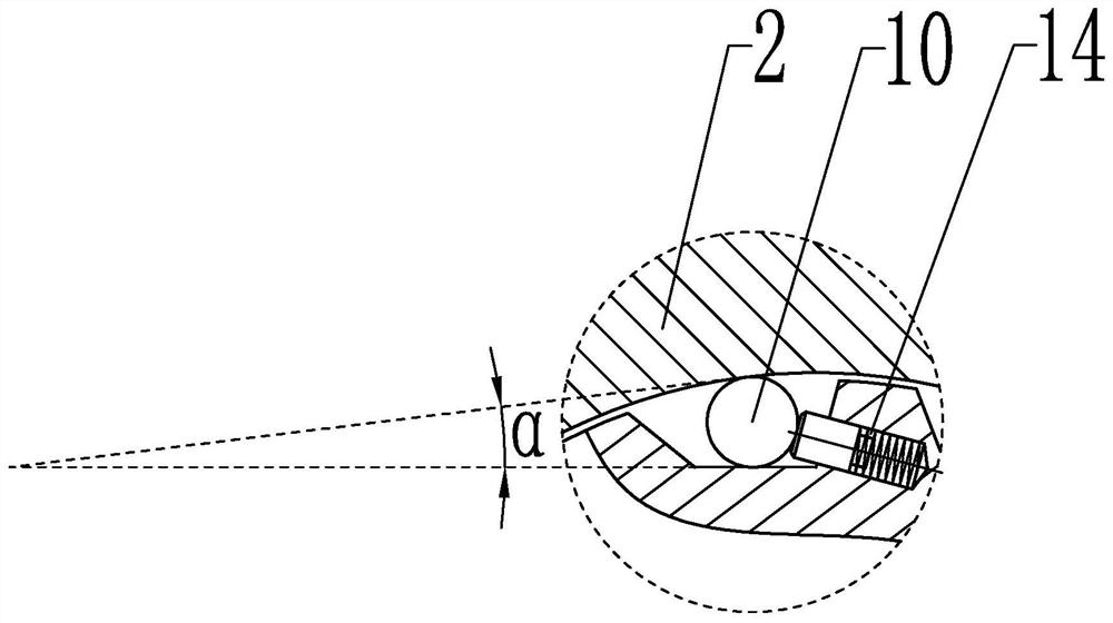
[0033] combine Figure 1 to Figure 6, this embodiment provides a centrifugal clutch, comprising: an inner ring member 1 engaged with the driving end, an outer ring member 2 engaged with the driven end, and a middle ring member 1 and the outer ring member 2 disposed between the inner ring member 1 and the outer ring member 2 between centrifuge assemblies 3. The inner ring member 1 and the outer ring member 2 are coaxially arranged, the centrifugal assembly 3 is always in driving connection with the inner ring member 1, and after the inner ring member 1 is rotated to reach the centrifugal condition, the centrifugal assembly 3 can be triggered at the same time with the outer ring member 2. Transmission connection to realize clutch operation between. A shell member 4 is arranged between the inner ring member 1 and the outer ring member 2 . The shell members 4 are respectively covered on the two outer end surfaces to form a closed inner cavity between the inner ring member 1 and ...


PUM


Abstract

The invention provides a centrifugal clutch. The centrifugal clutch comprises an inner ring piece connected with a driving end, an outer ring piece connected with a driven end and a centrifugal assembly arranged between the inner ring piece and the outer ring piece. The inner ring piece and the outer ring piece are coaxially arranged, the centrifugal assembly is in transmission connection with the inner ring piece all the time, and after the inner ring piece rotates to reach the centrifugal condition, the centrifugal assembly can be triggered to be in transmission connection with the outer ring piece at the same time, so that clutch operation between the inner ring piece and the outer ring piece is achieved; a shell part is arranged between the inner ring part and the outer ring part; the outer shell pieces cover the two outer side end faces respectively so that a closed inner containing cavity can be formed between the inner ring piece and the outer ring piece, liquid injection openings communicated with the inner containing cavity are formed in the outer shell pieces, and the centrifugal assembly is arranged in the inner containing cavity filled with lubricating liquid. In addition, friction, heat transfer and the like generated in the frequent joint movement process of the centrifugal assembly can be filled with the lubricating liquid through the inner containing cavity defined by the outer shell part to provide lubricating fit, and the clutch operation effect of a centrifugal mode is remarkably improved.

Description

technical field [0001] The present invention relates to the technical field of clutches, and in particular, to a centrifugal clutch. Background technique [0002] Existing clutches, especially one-way clutches, generally have two movement modes, one is torque transmission or engagement, and the other is idling or overrun. Its function is that when the power source drives the passive element, it can only transmit in one direction. If the power source changes direction, such as clockwise to counterclockwise, it will automatically disengage and slip, so that no power transmission function is generated. One-way clutches are used in various fields, such as chain drives of bicycles, starting of automobiles, automatic transmissions, and so on. [0003] At present, the commonly used one-way clutches are usually friction type one-way clutches, which are mainly in the form of friction plates, so that they have high requirements on the environment and working conditions of use. Becau...

Claims


Application Information

Patent Timeline
Patent Type & Authority Applications(China)
IPC IPC(8): F16D45/00
CPCF16D45/00F16D2300/0214
Inventor 熊鹏生董金进骆书芳林剑荣陶欢陈发根陈俊宏王辉丰飞赖文辉李曙杨龙丘友青赖永芳徐艳王雪莲陈志佳郑坤华李玉兰李德恒张代垚刘卓韬柴源吴炫增何洋林宏立黄锐鹏袁建
Owner XIAMEN SOUTH SUPER MACHINERY CO LTD
Learn More