a clutch structure
A technology of clutch shafts and mutual meshing, which is applied in clutches, mechanically driven clutches, and clutches that mesh with each other, and can solve the problems of complex clutch devices, increased costs, and low operational reliability
- Summary
- Abstract
- Description
- Claims
- Application Information
AI Technical Summary
Problems solved by technology
Method used
Image
Examples
Embodiment Construction
[0028] In order to make the above objectives, features, and advantages of the present invention more obvious and understandable, the following further describes the embodiments of the present invention in detail with reference to the accompanying drawings and specific implementations.
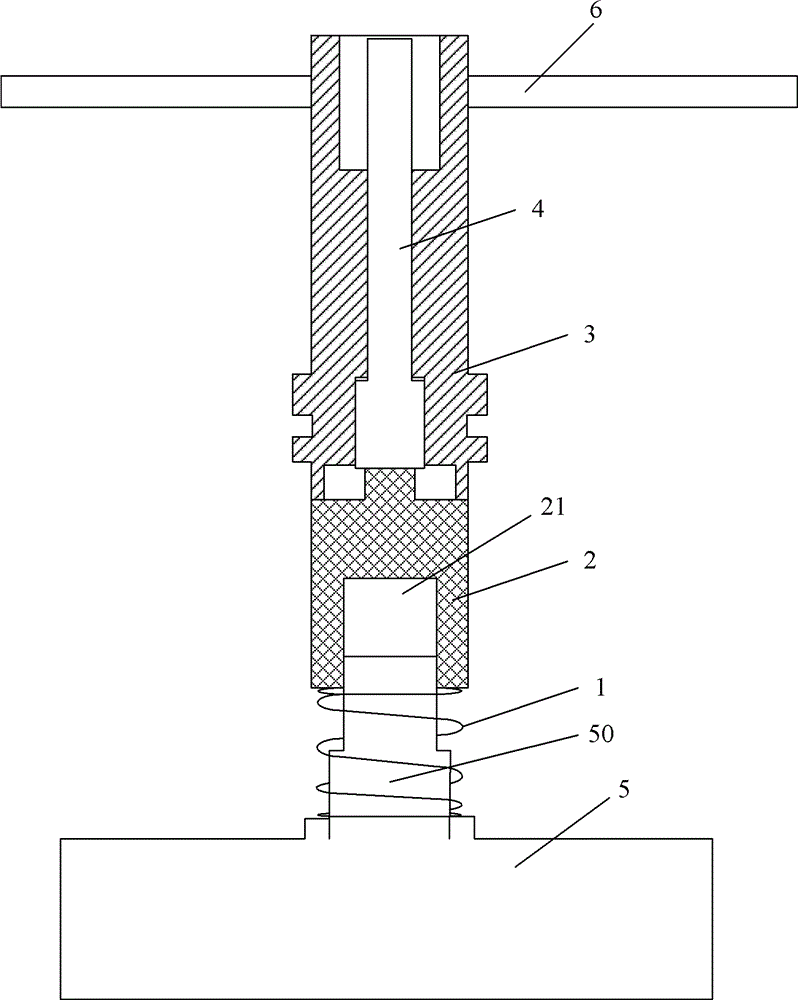
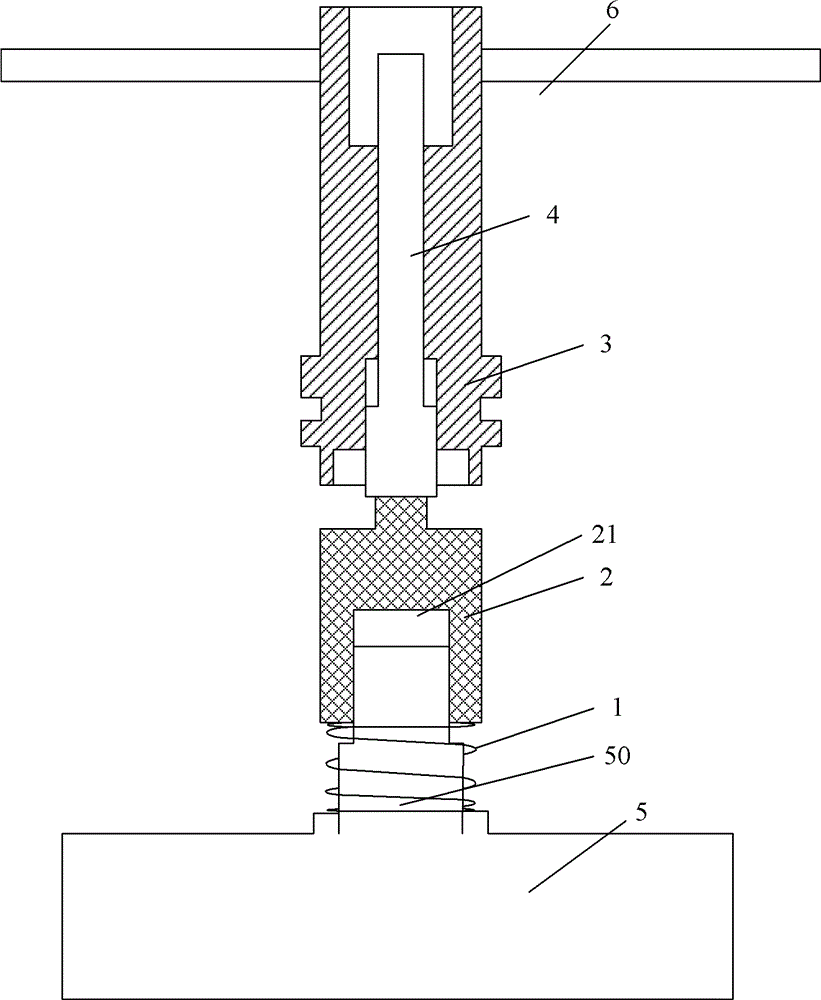
[0029] The present invention provides a clutch structure, such as figure 1 As shown, it includes: a return spring 1, a clutch shaft 2, a fixed rotating shaft 3 and a push rod 4.
[0030] The lower end surface of the clutch shaft 2 is provided with a groove 21 matched with the motor output shaft 50, and the clutch shaft 2 is sleeved on the motor output shaft 50 through the groove 21. Generally, the cross section of the motor output shaft 50 perpendicular to its axial direction is a square, and correspondingly, the shape of the groove 21 on the end face thereof is a square. The clutch shaft 2 can move along its axial direction.
[0031] The return spring 1 is sleeved on the motor output shaft 50, the l...
PUM
 Abstract
Description
Claims
Application Information
 - Generate Ideas
- Intellectual Property
- Life Sciences
- Materials
- Tech Scout
- Unparalleled Data Quality
- Higher Quality Content
- 60% Fewer Hallucinations
Browse by: Latest US Patents, China's latest patents, Technical Efficacy Thesaurus, Application Domain, Technology Topic, Popular Technical Reports.
© 2025 PatSnap. All rights reserved.Legal|Privacy policy|Modern Slavery Act Transparency Statement|Sitemap|About US| Contact US: help@patsnap.com


