
door handle mechanism

A handle and clutch mechanism technology, applied in the directions of wing leaf handles, handle connections, door/window accessories, etc., can solve the problem that the door handle mechanism does not have the clutch function of the clutch mechanism in the lock, and achieve the effect of realizing the clutch operation.

Active Publication Date: 2021-12-07
浙江王力安防产品有限公司
View PDF8 Cites 0 Cited by
  • Summary
  • Abstract
  • Description
  • Claims
  • Application Information

AI Technical Summary

Problems solved by technology

[0004] Therefore, the technical problem to be solved by the present invention is to overcome the locksets with internal clutch mechanisms in some lock heads in the prior art. The conventional door handle mechanism does not have the defect of driving the clutch mechanism in the lock head. A door handle mechanism that can drive the clutch mechanism inside the lock

Method used


Image

  • door handle mechanism
  • door handle mechanism
  • door handle mechanism

Examples


Embodiment Construction

[0030] The technical solutions of the present invention will be clearly and completely described below in conjunction with the accompanying drawings.

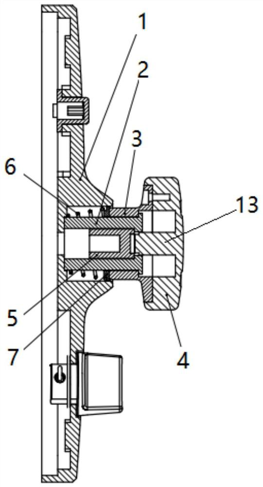
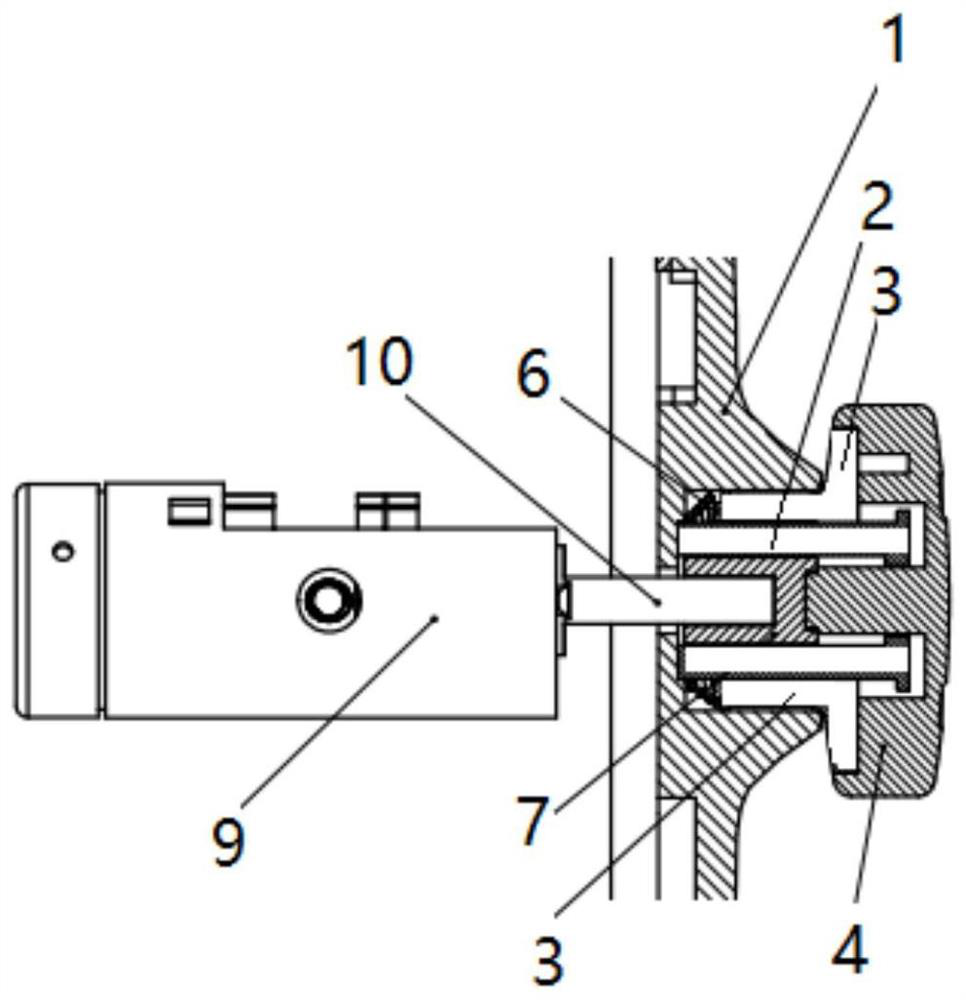
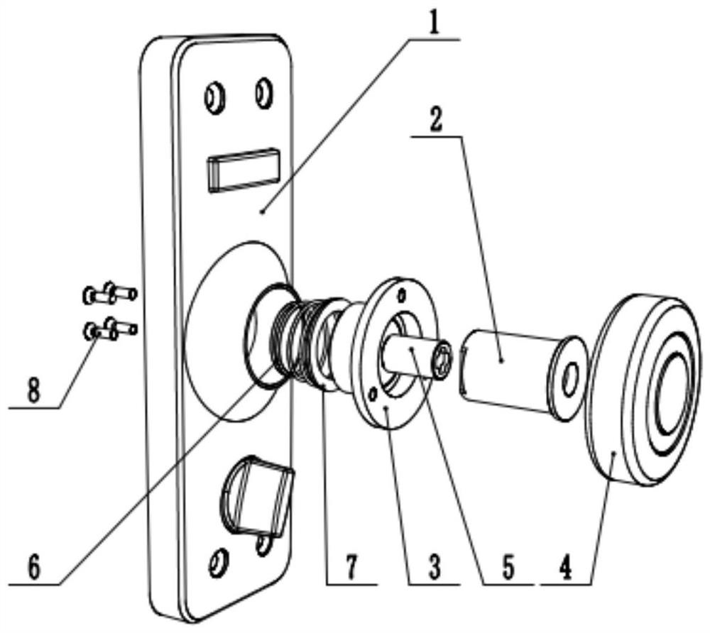
[0031] figure 1 It is a cross-sectional view of a door handle mechanism provided in an embodiment of the present invention; figure 2 for figure 1 A cross-sectional view of the combination of the provided door handle mechanism and the lock head 9; as figure 1 and figure 2 As shown, the present invention provides a door handle mechanism, which has a handle panel 1 , and a tubular member 2 with one end fixed to the handle panel 1 is arranged on the handle panel 1 . In this embodiment, the outer wall of the tubular member 2 constitutes the first guiding structure, and the inner wall of the tubular member 2 constitutes the second guiding structure. In this embodiment, the handle panel 1 is arranged perpendicular to the tubular member 2, that is, the guiding direction of the first guiding structure formed by the outer wall and...


PUM


Abstract

The present invention relates to the technical field of hardware products, and provides a door handle mechanism, including: a handle panel with a first guiding structure and a second guiding structure; the handle, constrained by the first guiding structure, can reciprocate in a direction perpendicular to the door panel, And it can drive the handle square shaft to rotate; the clutch part, connected to one end of the handle square shaft protruding from the lock head, can be rotatably arranged on the second guide structure around the rotation axis of the handle square shaft, and can be constrained by the second guide structure. Reciprocating movement along the rotation axis of the square shaft of the handle; a clutch mechanism is provided between the clutch and the handle, and the clutch action is realized through the reciprocating movement of the handle; the end of the square shaft of the handle extending to the lock head is connected to the inside of the lock head through axial movement. an inner clutch mechanism for clutching; and a biasing mechanism that applies a biasing force to the handle tending to disengage the clutch mechanism. The door handle mechanism provided by the invention can not only satisfy the function of a common handle, but also realize the clutch operation of driving the clutch mechanism inside the lock head.

Description

technical field [0001] The invention relates to the technical field of hardware products, in particular to a door handle mechanism. Background technique [0002] The applicant has previously applied for a door lock with a two-way clutch structure, which includes a lock box with a linkage switch dial inside; Mechanism; wherein the two-way clutch structure is connected between the linkage switch dial and the teletype dial; including, set opposite to the telex dial and linked with the linkage switch dial to realize unlocking or locking The driving dial of the lock; and a pair of clutch parts that can be detachably inserted into each other, one of the pair of clutch parts is a teletype clutch part that is slidably arranged in the teletype dial, and a pair of the clutch parts The other of the clutch parts is a rotary clutch part slidably installed in the driving dial. When the door lock is in the opening and closing state, the external transmission member extends from either si...

Claims


Application Information

Patent Timeline
Patent Type & Authority Patents(China)
IPC IPC(8): E05B1/00E05B3/00E05B13/00
CPCE05B1/003E05B3/00E05B13/005
Inventor 支崇铮
Owner 浙江王力安防产品有限公司
Learn More