Pump body applied to compressor and compressor

A compressor and pump body technology, applied in the field of compressors, can solve problems such as eccentric wear at the end contact between the crankshaft and the main bearing, insufficient bearing support rigidity, and eccentric wear at the end contact, so as to improve work reliability and eliminate Resonance, the effect of slowing down the eccentric wear of the crankshaft

Pending Publication Date: 2022-07-22
GUANGDONG MEIZHI COMPRESSOR
View PDF6 Cites 0 Cited by
  • Summary
  • Abstract
  • Description
  • Claims
  • Application Information

AI Technical Summary

Problems solved by technology

The above-mentioned 6f frequency noise problem has a high probability of occurrence in inverter air conditioners, especially when the motor power is increased. Some studies have found that this noise problem is related to the structural design of the pump body of the compressor. The specific reason is the crankshaft of the pump body. Resonance, in addition, after long-term operation of the compressor, eccentric wear occurs at the contact between the crankshaft and the end of the main bearing
[0003] Existing compressors use main and auxiliary double bearings to support the crankshaft of the pump body. This double bearing support method is the main factor that causes the problems of crankshaft resonance and eccentric wear. The crankshaft runs in a tilted state for a long time, and eccentric wear occurs at the end contact between the crankshaft and the main bearing and the auxiliary bearing; on the other hand, the bearing support rigidity is insufficient, so that the natural frequency of the crankshaft whirling vibration falls to 6 times of the compressor rotation frequency In the excitation frequency range, crankshaft resonance is prone to occur

Method used


Image

  • Pump body applied to compressor and compressor
  • Pump body applied to compressor and compressor
  • Pump body applied to compressor and compressor

Examples


Embodiment Construction

[0041] The following describes in detail the embodiments of the present invention, examples of which are illustrated in the accompanying drawings, wherein the same or similar reference numerals refer to the same or similar elements or elements having the same or similar functions throughout. The embodiments described below with reference to the accompanying drawings are exemplary, only used to explain the present invention, and should not be construed as a limitation of the present invention.

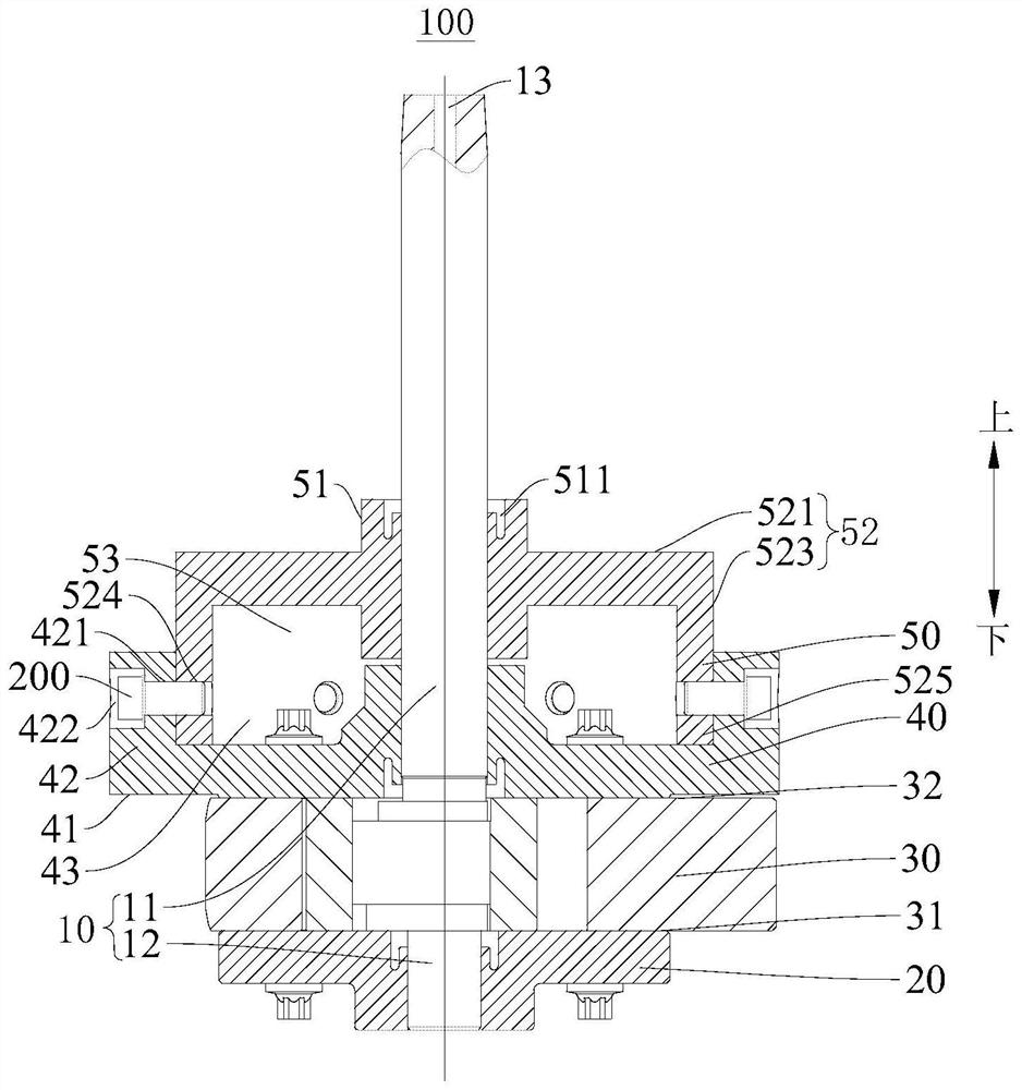
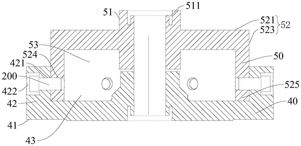
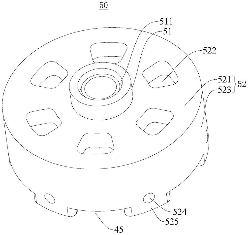
[0042] Reference below Figure 1-Figure 4 A pump body 100 applied to a compressor according to an embodiment of the present invention is described. The pump body 100 is composed of a crankshaft 10, a cylinder 30, a first support bearing 20, a second support bearing 40 and a third support bearing 50. The first support bearing 20. The second support bearing 40 and the third support bearing 50 are sleeved on the crankshaft 10 , the first support bearing 20 , the second support bearing 40 a...


PUM


Abstract

The pump body comprises a crankshaft and an air cylinder, the crankshaft penetrates through the air cylinder, and the air cylinder is provided with a first end and a second end which are opposite to each other; the first supporting bearing is arranged at the first end and sleeves the crankshaft; the second supporting bearing is arranged at the second end and sleeves the crankshaft; the third supporting bearing is arranged on the side, away from the air cylinder, of the second supporting bearing, and the third supporting bearing is connected with the second supporting bearing and arranged on the crankshaft in a sleeving mode. Therefore, the crankshaft is supported by the first supporting bearing, the second supporting bearing and the third supporting bearing at the same time, the supporting rigidity of the crankshaft is effectively improved, the inherent frequency of crankshaft whirling vibration is moved out of the unbalanced radial electromagnetic force fundamental frequency range in the rotating speed interval of the compressor, crankshaft whirling vibration resonance is eliminated, and the noise of the compressor is reduced; the stress state of each supporting bearing can be improved, eccentric wear of the crankshaft is relieved, and the working reliability of the compressor is improved.

Description

technical field [0001] The present invention relates to the field of compressors, in particular to a pump body applied to the compressor and a compressor having the pump body applied to the compressor. Background technique [0002] In the related art, the compressor often has abnormally high noise value at a certain frequency. Analysis shows that the abnormal noise frequency is 6 times the compressor rotational frequency (hereinafter referred to as 6f, where f is the rotational frequency). The above-mentioned 6f frequency noise problem has a high probability of occurrence in inverter air conditioners, especially when the motor power is increased. Some studies have found that this noise problem is related to the structural design of the pump body of the compressor. The specific reason is the crankshaft of the pump body. Resonance, in addition, eccentric wear occurs at the contact between the crankshaft and the end of the main bearing after the compressor has been operated for...

Claims


Application Information

Patent Timeline
IPC IPC(8): F04B39/00F16C9/02F16C35/00F04B39/02
CPCF04B39/0027F16C9/02F16C35/00F04B39/0094F04B39/0246
Inventor 张赣波陈涛陈宗平
Owner GUANGDONG MEIZHI COMPRESSOR
Why Eureka
Try Eureka