
Extra-high voltage pile

A technology of ultra-high voltage electricity and electric piles, which is used in the installation of electrical components, cables, towers, etc., and can solve problems such as easy deformation, hidden dangers, and increased cable stress.

Inactive Publication Date: 2022-07-22
沈炫平
View PDF0 Cites 0 Cited by
  • Summary
  • Abstract
  • Description
  • Claims
  • Application Information

AI Technical Summary

Problems solved by technology

[0003] The existing ultra-high voltage electric piles are generally high in height and are fixed by bolts during installation. However, if the installation bolts are not fixed in place during installation, the center of gravity of the electric pile will shift, and the side of the shift will be stressed when it is used for a long time The force-bearing side is easy to deform, causing the entire electric pile to deform, which has a greater safety hazard, and the connection cable between the electric piles is long during use, so that the cable cannot be kept in a horizontal state, and the center of the cable will be In the cold season, when the water source freezes and adheres to the outside of the cable, the force on the cable itself will increase. When the force limit of the cable is reached, the cable will be broken, which is a huge safety hazard. So be badly in need of a kind of device to solve the above problems

Method used


Image

  • Extra-high voltage pile
  • Extra-high voltage pile
  • Extra-high voltage pile

Examples


Embodiment Construction

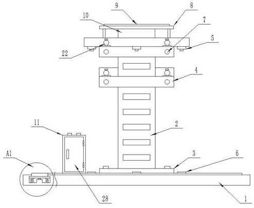
[0027] The technical solutions in the embodiments of the present invention will be clearly and completely described below with reference to the accompanying drawings in the embodiments of the present invention. Obviously, the described embodiments are only a part of the embodiments of the present invention, but not all of the embodiments. Based on the embodiments of the present invention, all other embodiments obtained by those of ordinary skill in the art without creative efforts shall fall within the protection scope of the present invention.

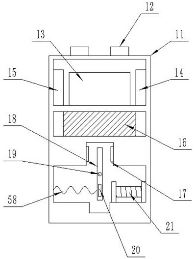
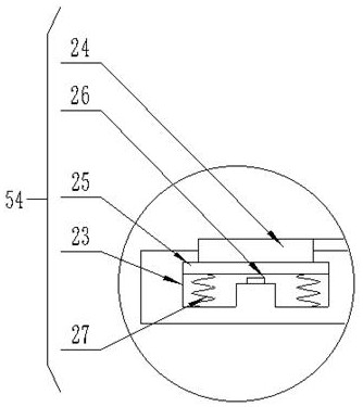
[0028] see Figure 1-7 , The present invention provides a technical solution: an ultra-high voltage electric pile, comprising a pre-embedded board 1 and an electric pile main body 2, the top of the pre-embedded board 1 is fixedly provided with a cabinet 11, and the pre-embedded board 1 is internally provided with a first A trigger mechanism 54, a fixing frame 4 is fixedly arranged at the top of the electric pile main body 2, a cable 7...


PUM


Abstract

The invention discloses an extra-high voltage electric pile which comprises a pre-embedded plate and an electric pile body, a cabinet body is fixedly arranged at the top end of the pre-embedded plate, a first trigger mechanism is arranged in the pre-embedded plate, a fixing frame is fixedly arranged at the top end of the electric pile body, and a cable is fixedly arranged on one side of the fixing frame. A supporting frame is fixedly arranged at the top end of the fixing frame at the top end, a solar cell panel is fixedly arranged at the top end of the supporting frame, and a first storage battery is fixedly arranged at the bottom end of the supporting frame. A first semicircular ring and a second semicircular ring which are spliced assist in supporting a cable, and when the cable is frozen, the weight is increased at the moment, so that the cable extrudes an arc-shaped plate to drive a thin rod to move downwards along a thick rod and extrude a third spring until the thin rod extrudes a fourth control switch, and an electric signal is transmitted into a control box; therefore, the control box starts the motor, the electric heating pipe performs deicing work on the cable, manual starting is not needed, and the automatic deicing effect is achieved.

Description

technical field [0001] The invention relates to the field of ultra-high voltage electric piles, in particular to an ultra-high voltage electric pile. Background technique [0002] The English abbreviation of UHV is UHV; the voltage symbol is U (represented by V in some places); the unit of voltage is volt, and the unit symbol is also V; larger than volts are kV (kilovolt) and mV (millivolt) smaller than volts. , uV (microvolts), and there are kilobits between them. In my country, UHV refers to the voltage level of ±800 kV and above for direct current and 1000 kV and above for alternating current. [0003] The existing UHV electric piles are generally high in height, and are fixed by bolts during installation. However, if the installation bolts are not fixed in place during installation, the center of gravity of the electric piles will be offset, and the offset side will be stressed during long-term use. It makes the stressed side easy to deform, causing the entire electric...

Claims


Application Information

Patent Timeline
Patent Type & Authority Applications(China)
IPC IPC(8): E04H12/00E04H12/22H02G7/16G08B21/02G08B21/22
CPCE04H12/00E04H12/22H02G7/16G08B21/02G08B21/22
Inventor 沈炫平
Owner 沈炫平
Learn More