Concrete preparation device and use method thereof
A preparation device and concrete technology, applied in clay preparation device, mixing operation control device, mixing operation control, etc., can solve problems such as affecting screening and insufficient crushing, achieve fast and convenient material preparation and processing, and reduce material transfer operations Effect
- Summary
- Abstract
- Description
- Claims
- Application Information
AI Technical Summary
Problems solved by technology
Method used
Image
Examples
Embodiment 1
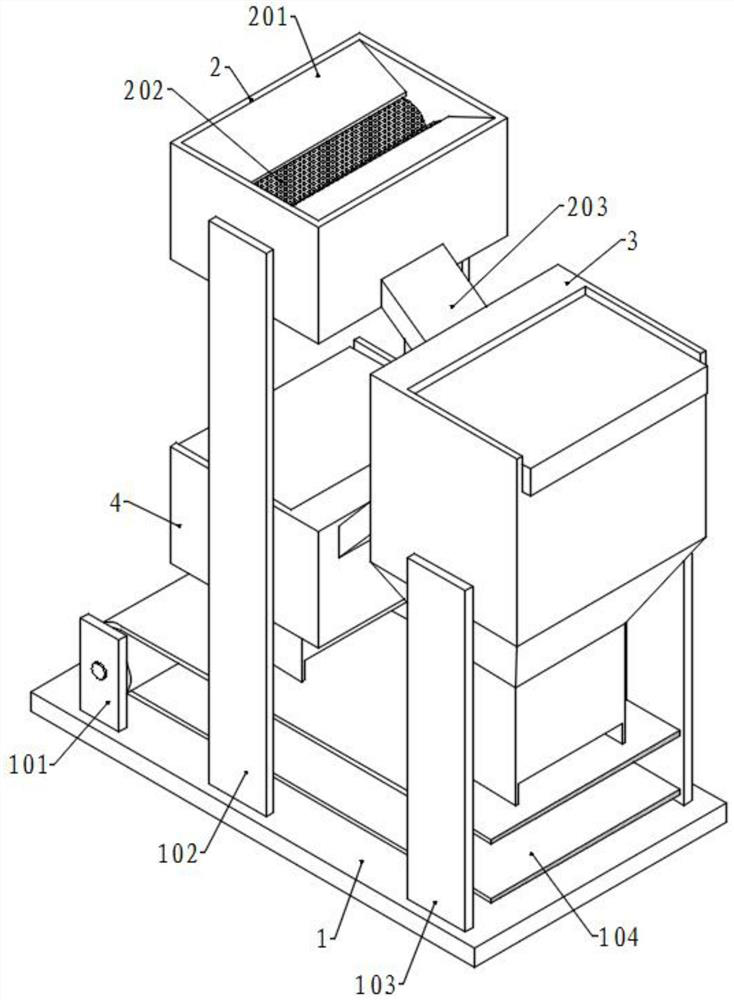
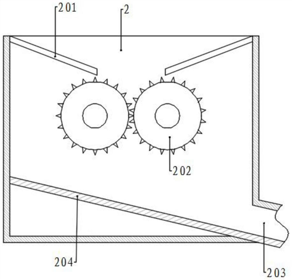
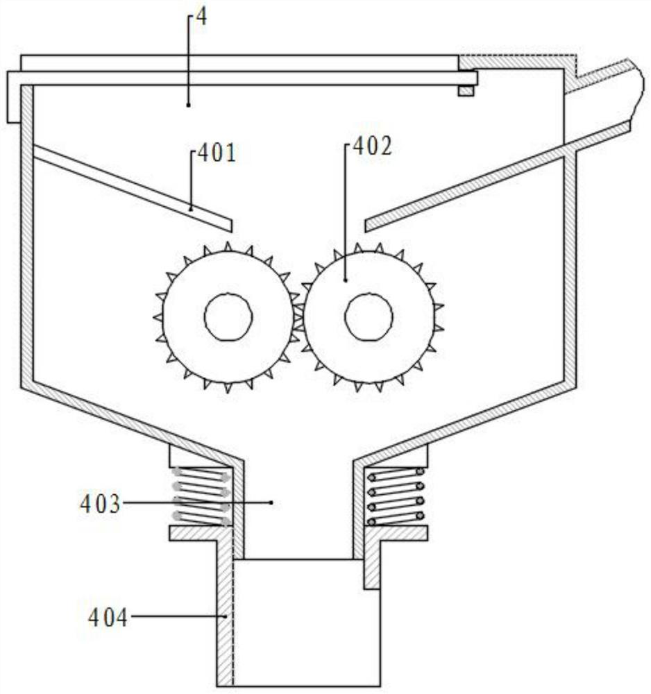
[0035] Referring to the drawings, the present invention provides a technical solution: a concrete preparation device, comprising a base 1, two first support plates 101 are symmetrically fixed on the rear side of the top surface of the base 1, and two vertical support plates 101 are symmetrically fixed in the middle. A straight second support plate 102, two third support plates are symmetrically fixed on the front side, a conveying wheel is rotatably connected between the two first support plates 101, a conveying belt 103 is arranged on the conveying wheel, and one end of the conveying wheel is connected There is a motor, a first crushing component is arranged between the upper parts of the two second support plates 102, and a second crushing component is arranged between the lower parts, and the second crushing component is located above the conveyor belt 103. A screening box 3 is fixed between the upper parts, and the screening box 3 is located at the middle front position of ...
Embodiment 2
[0047] The structure of this embodiment is basically the same as that of the first embodiment, the difference is that the bottom of the second material tube 403 is sleeved with a spring tube 404, the top of the spring tube 404 is fixed with bosses on both sides, and the boss is connected to the second material tube 403. A spring is connected between the bottom of the crushing box 4, the bottom end of the spring tube 404 is close to the top surface of the conveyor belt 103, and the lower part of the front side wall is provided with a notch, which is formed by the rear side wall and the left and right side walls of the spring tube 404. The material stop structure prevents the material from falling to the rear position, etc., falling from the conveyor belt 103, and after the material falls on the conveyor belt 103, with the movement of the conveyor belt 103, it passes through the front side notch of the spring tube 404. Send out.
Embodiment 3
[0049] The structure of the present embodiment is basically the same as that of the first embodiment, the difference is that the two ends of the screen box 3 corresponding to the screen plate 5 are provided with sealing plates 305, and the sealing plates 305 are located between the two baffles 304, and the two The upper parts of the opposite sides of the sealing plate 305 are respectively fixed with bumps 306, and the other side is evenly fixed with a plurality of guide shafts 307. spring.
[0050] When the push plate 503 pushes the material to move to the sealing plate 305 on one side, the push plate 503 contacts with the bumps 306 on the sealing plate 305 and makes the compression spring of the sealing plate 305 move, opening the end of the sieve plate 5 so that by pushing The plate 503 makes the material fall into the feeding chute 301. When the push plate 503 returns to its original position and is disengaged from the sealing plate 305, the sealing plate 305 contacts the e...
PUM
 Abstract
Description
Claims
Application Information
 - R&D
- Intellectual Property
- Life Sciences
- Materials
- Tech Scout
- Unparalleled Data Quality
- Higher Quality Content
- 60% Fewer Hallucinations
Browse by: Latest US Patents, China's latest patents, Technical Efficacy Thesaurus, Application Domain, Technology Topic, Popular Technical Reports.
© 2025 PatSnap. All rights reserved.Legal|Privacy policy|Modern Slavery Act Transparency Statement|Sitemap|About US| Contact US: help@patsnap.com


