Furnace tube inner support welding equipment for solar cell silicon wafer diffusion

A technology for solar cells and welding equipment, applied in welding equipment, auxiliary welding equipment, welding/cutting auxiliary equipment, etc., can solve problems affecting the accuracy of the furnace tube, the thermometer cannot be completely inserted into the bracket horizontally, and the service life of experimental measuring equipment is affected. , to achieve the effect of easy installation

Pending Publication Date: 2022-07-22
湖州学院
View PDF1 Cites 0 Cited by
  • Summary
  • Abstract
  • Description
  • Claims
  • Application Information

AI Technical Summary

Problems solved by technology

[0006] 2. When welding the brackets in this scheme, because the brackets are initially positioned in the furnace tube and then sent into the furnace tube for welding, it is easy to appear that multiple sets of brackets after welding cannot be kept on the same level, resulting in the thermometer not being able to Insert horizontally into the reserved hole at the bracket, and even the thermometer cannot be completely inserted into the bracket horizontally, which affects the accuracy of real-time temperature measurement in the furnace tube
[0007] 3. The manual welding of the brackets used in this scheme cannot guarantee that the brackets welded each time can be welded at a fixed distance, resulting in a lack of support for the equipment when the equipment for precision measurement of real-time data in the furnace tube is installed later. Inhomogeneity affects the service life of experimental measuring equipment

Method used


Image

  • Furnace tube inner support welding equipment for solar cell silicon wafer diffusion
  • Furnace tube inner support welding equipment for solar cell silicon wafer diffusion
  • Furnace tube inner support welding equipment for solar cell silicon wafer diffusion

Examples


Embodiment 1

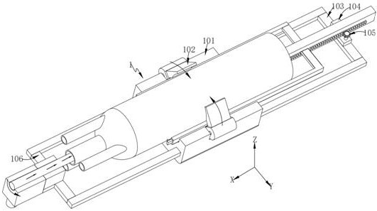
[0082] like Figure 1-2 As shown, a furnace tube inner bracket welding equipment for solar cell silicon wafer diffusion includes:

[0083] positioning unit 1;

[0084] a feeding unit 2, the feeding unit 2 is provided in the furnace tube positioned by the positioning unit 1; and

[0085] Welding unit 3, the welding unit 3 for welding the bracket to the inner wall of the furnace tube is provided on the side of the feeding unit 2;

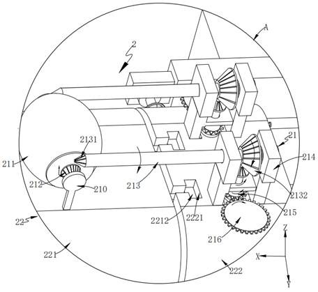
[0086] The feeding unit 2 includes:

[0087] a lift assembly 22 for adjusting the contact state of the clutch roller 211 with the furnace tube to drive the feeding unit 2 to move in a linear direction along the furnace tube; and

[0088] The driving component 21 is arranged on the upper part of the lifting component 22 for automatically driving the welding unit 3 to perform fixed-length welding work.

[0089] as an improvement, such as figure 2 As shown, the positioning unit 1 includes:

[0090] stage 101;

[0091] The splint 102, the splint 1...

Embodiment 2

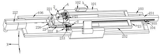
[0149] like Figure 7-10 As shown, the same or corresponding components as those in the first embodiment are given the corresponding reference numerals as in the first embodiment. For the sake of brevity, only the points of difference from the first embodiment are described below. The difference between the second embodiment and the first embodiment is:

[0150] As an improvement, the feeding unit 2 further includes a push-pull assembly 23;

[0151] The push-pull assembly 23 includes a transmission rod 231;

[0152] an auxiliary frame 232, the auxiliary frame 232 is connected to the upper position of the side of the transmission rod 231;

[0153] The heater 233 is connected to the end of the auxiliary frame 232 .

[0154] Further, the heater 233 installed at the end of the auxiliary frame 232 is aligned with the welding unit 3;

[0155] A guide groove is provided on the outside of the auxiliary frame 232 and inside the positioning unit 1 .

[0156] It should be noted that...


PUM


Abstract

The invention provides furnace tube inner support welding equipment for solar cell silicon wafer diffusion. The furnace tube inner support welding equipment comprises a positioning unit; the feeding unit is arranged in the furnace tube positioned by the positioning unit; the welding unit for welding a bracket to the inner side wall of the furnace tube is arranged at the side part of the feeding unit; the lifting assembly is used for adjusting the contact state of the clutch roller and the furnace tube so as to drive the feeding unit to move along the furnace tube in the linear direction; the driving assembly is arranged on the upper portion of the lifting assembly and used for automatically driving the welding unit to conduct fixed-length welding work. The clutch roller and the transfer wheel are in contact with the inner wall of the furnace tube and are matched with the driving mechanism and the driving wheel to clamp the conveying rod, it is ensured that the combination of the driving assembly and the lifting assembly always keeps straight running during moving, and therefore the purposes that installation is convenient, and multiple sets of welded supports can be kept on the same horizontal plane are achieved.

Description

technical field [0001] The invention relates to the technical field of furnace tube inner bracket installation, in particular to a furnace tube inner bracket welding device for solar cell silicon wafer diffusion. Background technique [0002] The furnace tube used for silicon wafer diffusion in solar cells is mainly made of quartz material, with a transparent tubular appearance, and four sets of pipes are arranged at the furnace door of the furnace tube, among which one set of main pipelines for feeding materials is set at the furnace door In the middle, the other three sets of pipes for gas introduction are arranged in a ring along the main pipe. During the processing of the furnace tube, due to the smooth curved surface of the inner wall of the furnace tube, it is impossible to place some measuring equipment such as a thermometer inside the furnace tube during use. To measure the real-time temperature and other data in the furnace tube, it is usually necessary to weld mult...

Claims


Application Information

Patent Timeline
IPC IPC(8): B23K37/00
CPCB23K37/00Y02P70/50
Inventor 陈建清
Owner 湖州学院
Why Eureka
Try Eureka