
Continuous flow reactor with controllable residence time and design and use method thereof

A residence time and reactor technology, applied in chemical instruments and methods, fluid mixers, mixers, etc., can solve the problems of short residence time of reactants, high microchannel pressure, and low reaction efficiency, and it is not easy to achieve residence time. Control, the effect of easy control of residence time

Active Publication Date: 2022-07-22
FUZHOU UNIV +1
View PDF1 Cites 0 Cited by
  • Summary
  • Abstract
  • Description
  • Claims
  • Application Information

AI Technical Summary

Problems solved by technology

[0003] For example, Chinese patent CN215611613U points out that the continuous flow reactor has poor mixing effect under the condition of low flow rate (the fluid in the channel is laminar flow at low flow rate, and the vortex phenomenon is not obvious); although the mixing effect is good under the condition of high flow rate, the reactants The residence time in the pipeline is short, which cannot meet the requirement of reaction time, resulting in the problem of low reaction efficiency
[0004] The published paper (Zhao Chenxi, T-type microchannel device preparation of monodisperse chitosan microspheres and its in vitro drug release performance. Beijing University of Chemical Technology) pointed out: there are high viscosity, high pressure in the microchannel, and different flow patterns in the channel. Stable, and easy to cause problems such as wear and tear on equipment
[0005] In addition, in the current continuous flow microchannel reactor, the viscosity of the material in the microchannel only stays at the mPa·s level, and there are few researches and achievements on high-viscosity and ultra-high-viscosity materials.
[0006] In terms of structure, conventional microchannel reactors are mainly coiled tubes, but the length of coiled tubes required for continuous operation is extremely large and the cost is high

Method used

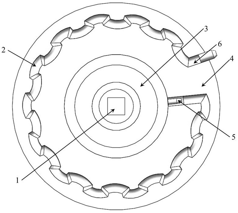
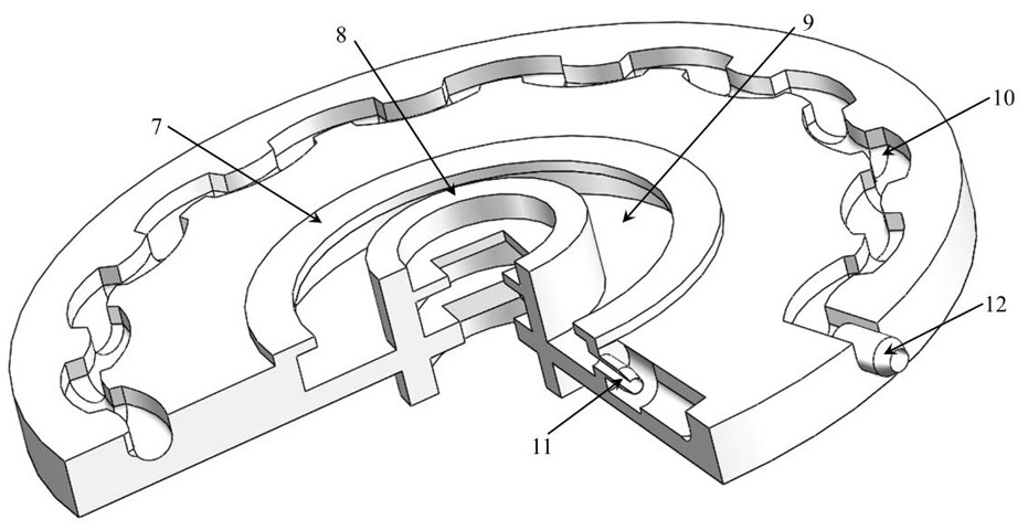
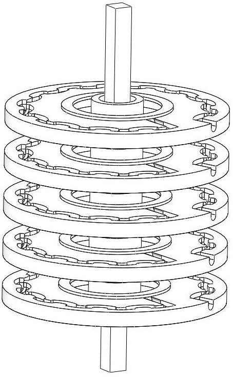

Image

  • Continuous flow reactor with controllable residence time and design and use method thereof
  • Continuous flow reactor with controllable residence time and design and use method thereof
  • Continuous flow reactor with controllable residence time and design and use method thereof

Examples


example 1

[0063] Sodium alginate with a viscosity of 2.52Pa·s was added to the ink as the test medium. The test medium is pumped into the liquid storage chamber 3 as a buffer through the peristaltic pump, and the test medium enters the reaction channel through the channel inlet under the action of centrifugal force. Change the motor speed to get as Figure 4 results shown. In the figure, (a), (b), (c) are the conditions of small rotation speed, and (d), (e), and (f) are conditions of large rotation speed. Depend on Figure 4 It can be known that the residence distribution of the two situations in the channel can be achieved by changing the motor speed, and the material residence time can be controlled by controlling the inlet speed of the material.

example 2

[0065] Nano-silver was prepared by using 15Pa·s sodium alginate and silver nitrate as reactants, and the reaction was carried out at 80℃ in a continuous flow reactor with controllable residence time. The sodium alginate and silver nitrate are mixed uniformly at room temperature, and the sodium alginate and silver nitrate basically do not react at this temperature. The mixture is pumped into the buffer by the peristaltic pump, and the test medium enters the reaction channel through the channel inlet under the action of centrifugal force. The motor speed was kept at 1000rpm for 30min.

[0066] Figure 5 It is the XRD pattern of nano-silver, which shows the X-ray diffraction pattern of the reaction of 0.05mol / L silver nitrate and sodium alginate to produce nano-silver. The crystal planes (111), (200), (220) and (311) in the figure are consistent with the 04-0783 silver in the standard card JCPDS, indicating that the nano-silver generated by the reaction has a face-centered...


PUM


Abstract

The invention provides a continuous flow reactor with controllable retention time and a design and use method thereof. The continuous flow reactor comprises a rotating shaft and n cavity channels which are fixedly arranged around the rotating shaft and are connected end to end. Combination of a centrifugal force field and a micro (milli) channel is achieved. The transmission interface is expanded through the structural design of the micro-channel; under the action of a centrifugal force field, vortex can be generated in the channel when the net flow velocity is relatively low or even zero, so that a relatively good mixing effect is realized; by designing the channel structure, the residence time in the channel can be controlled; through simple longitudinal stacking and series connection, continuous flow can be easily realized. The reactor has a particularly obvious treatment effect on high-viscosity materials.

Description

technical field [0001] The invention belongs to the technical field of microchannel reactors and rotating equipment, and in particular relates to a continuous flow reactor with controllable residence time and a design and use method thereof. Background technique [0002] The traditional batch kettle production method has shortcomings such as low mass transfer and heat transfer efficiency, poor product quality stability, and low production efficiency. The continuous flow reactor can solve this problem very well. In recent years, continuous flow reactors have been widely used in chemical, pharmaceutical, new materials and other fields. Research on continuous flow reactors mainly focuses on microchannel reactors, but there are still some shortcomings and improvements in continuous flow microchannel reactors at this stage: [0003] For example, Chinese patent CN215611613U pointed out that the mixing effect of continuous flow reactor is poor at low flow rate (the fluid in the c...

Claims


Application Information

Patent Timeline
Patent Type & Authority Applications(China)
IPC IPC(8): B01J19/00B01F25/10
CPCB01J19/0046B01J19/0093B01J19/0053B01J19/0006
Inventor 严佐毅朱晓磊郑辉东
Owner FUZHOU UNIV
Learn More