Damping glue mounting structure, lens drive device, camera device, electronic products
A technology of a lens driving device and an installation structure, which is applied in the fields of electronic products, photographic devices, damping glue installation structures, and lens driving devices, can solve the problem of inaccurate placement of the damping glue, the vibration of the carrier relative to the base, and the easy throwing of the damping glue. To avoid problems such as detachment, avoid the outflow of glue, facilitate dispensing, and increase the dispensing entrance.
- Summary
- Abstract
- Description
- Claims
- Application Information
AI Technical Summary
Problems solved by technology
Method used
Image
Examples
Embodiment 1
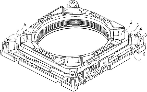
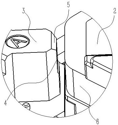
[0034] Embodiment 1: as Figure 1 to Figure 6 As shown, a damping glue installation structure proposed by the present invention includes a base 1 and a carrier 2. The edge of the base 1 is integrally formed with a bracket 3. There are four brackets 3 and they are respectively located at the corners of the base 1. The brackets 3 is a plane toward the center of the carrier 2 . There is a gap between the side wall of the carrier 2 and the bracket 3, and the bracket 3 is provided with a gap 4 for storing glue toward the side wall of the carrier 2, and the gap 4 extends to the side of the bracket 3 away from the base 1. At one end, damping glue is provided at the position of the notch 4 . When dispensing damping glue, the damping glue is set at the position of the gap 4, and the damping glue is in contact with the carrier 2 on the opposite side, so that the damping glue can play a corresponding damping effect between the carrier 2 and the bracket 3; because the bracket 3 A notch ...
Embodiment 2
[0038] Embodiment 2, compared with embodiment 1, differs in that: as Figure 7 As shown, the notch 4 is in the shape of a groove, and the sides of the notch 4 do not extend to the edge of the bracket 3 . In this structure, the damping glue can be restricted from being thrown out by the sides on both sides of the notch 4 , and the damping glue can be ensured to be located at the notch 4 .
Embodiment 3
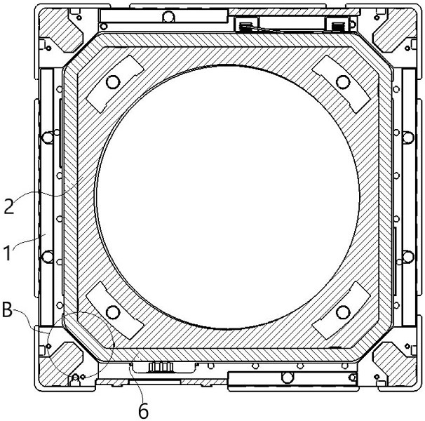
[0039] Embodiment 3: a kind of lens driving device, such as Figure 8 to Figure 10 As shown, it has the damping glue installation structure described in Embodiment 1, and a glue dispensing groove 7 for fixing the coil 6 is opened on the side wall of the carrier 2, that is, the glue dispensing groove 7 is located between the carrier 2 and the coil 6, and the glue dispensing groove 7 extends to the end of the carrier 2 away from the base 1 . When the coil 6 is installed on the carrier 2, glue is dispensed at the position of the dispensing tank 7, and the glue remains in the dispensing tank 7 and contacts the coil 6, so as to realize the dispensing and fixing of the coil 6, and prevent the glue from flowing out, and play a role of storage Glue effect.
[0040] An inclined surface 8 is provided between the glue dispensing groove 7 and an edge of the carrier 2 facing away from the base 1 to facilitate the flow of glue into the glue dispensing groove 7 . The glue dispensing inlet ...
PUM
 Abstract
Description
Claims
Application Information
 - Generate Ideas
- Intellectual Property
- Life Sciences
- Materials
- Tech Scout
- Unparalleled Data Quality
- Higher Quality Content
- 60% Fewer Hallucinations
Browse by: Latest US Patents, China's latest patents, Technical Efficacy Thesaurus, Application Domain, Technology Topic, Popular Technical Reports.
© 2025 PatSnap. All rights reserved.Legal|Privacy policy|Modern Slavery Act Transparency Statement|Sitemap|About US| Contact US: help@patsnap.com


