
Defoaming filter

A filter and defoaming technology, which is applied in the direction of filtration separation, filtration circuit, chemical instruments and methods, etc., can solve the problems of easy generation of air bubbles in oil, reduce the service life of equipment, and cavitation, so as to improve the defoaming effect and increase the Effect of large contact area and expanded defoaming range

Pending Publication Date: 2022-07-22
无锡市海卓力克液压机械有限公司
View PDF0 Cites 0 Cited by
  • Summary
  • Abstract
  • Description
  • Claims
  • Application Information

AI Technical Summary

Problems solved by technology

[0006] Aiming at the deficiencies in the prior art, the present invention provides a defoaming filter to solve the problems in the prior art that the oil in the filter is prone to generate air bubbles, thereby causing cavitation and reducing the service life of the equipment

Method used


Image

  • Defoaming filter
  • Defoaming filter
  • Defoaming filter

Examples


Embodiment

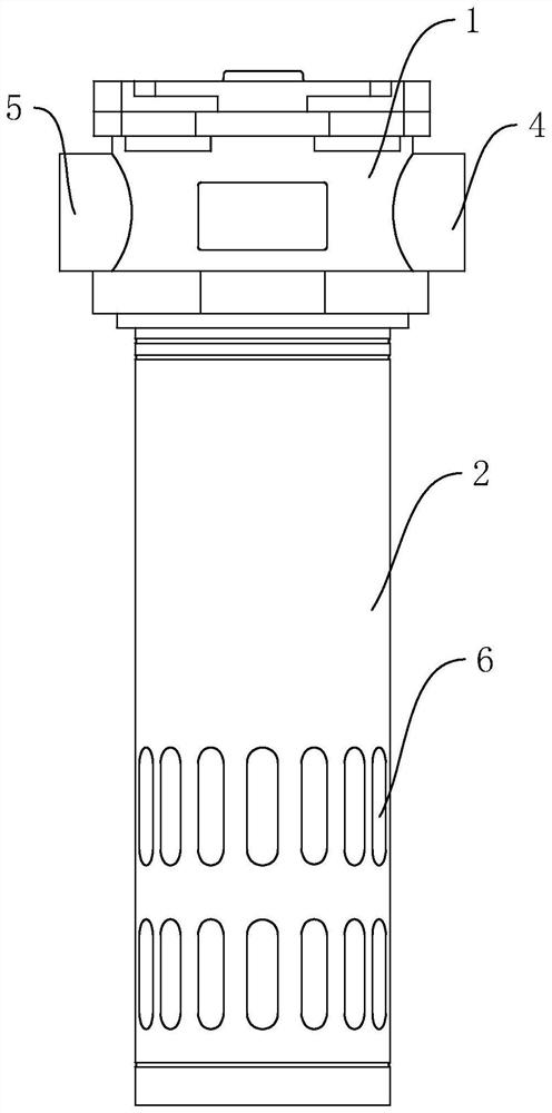
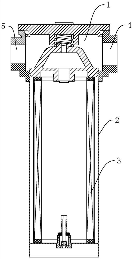
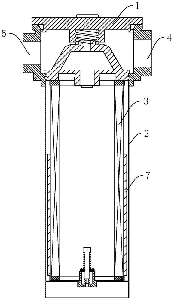
[0033] refer to Figure 3-4 , which is a defoaming filter disclosed in the present invention, comprising a filter head 1 , a filter cartridge 2 and a filter element 3 . The filter head 1 is provided with an oil inlet 4 and a sensor connection port 5, the oil inlet 4 is the inlet for the oil to enter the filter, and the sensor connection port 5 is used to connect the sensor used with the filter. The filter cartridge 2 and the filter element 3 are both cylindrical, the filter cartridge 2 and the filter element 3 are connected with the filter head 1, the filter element 3 is located inside the filter cartridge 2, the filter element 3 is communicated with the filter head 1, and the bottom of the side wall of the filter cartridge 2 Several oil outlet holes 6 are provided.

[0034] The bottom of the filter element 3 is sleeved with a defoaming filter screen cartridge 7, which is located between the filter element 3 and the filter cartridge 2, and the position of the defoaming filter...


PUM


Abstract

The invention relates to a defoaming filter which comprises a filter head, a filter cartridge and a filter element, an oil inlet is formed in the filter head, the filter cartridge and the filter element are both connected with the filter head, the filter element is located in the filter cartridge and communicated with the filter head, a plurality of oil outlet holes are formed in the bottom of the side wall of the filter cartridge, the bottom of the filter element is sleeved with a defoaming filter screen cylinder, and the defoaming filter screen cylinder is located between the filter element and the filter cartridge. The position of the defoaming filter screen cylinder corresponds to the position of the oil outlet hole, and the diameter of a filter hole in the defoaming filter screen cylinder is 100-150 microns. During use, oil enters the filter head from the oil inlet, then enters the filter element, then penetrates through the filter element and the defoaming filter screen cylinder to enter the space between the filter element and the filter cylinder, and finally is discharged out of the filter cylinder through the oil outlet hole; bubbles existing in oil can be dispersed into small bubbles or directly eliminated by the filtering holes densely distributed in the defoaming filter screen cylinder, so that the defoaming filter screen cylinder has the advantages that cavitation can be avoided, and the service life of the defoaming filter screen cylinder is prolonged.

Description

technical field [0001] The invention relates to the technical field of filters, in particular to a defoaming filter. Background technique [0002] The filter is an indispensable device on the conveying medium pipeline, which is mainly used to filter the impurities and pollutants in the medium. [0003] like Figure 1-2 Shown is a filter in the prior art, including a filter head 1, a filter cartridge 2 and a filter element 3, the filter head 1 is provided with an oil inlet 4 and a sensor connection port 5, and the oil inlet 4 is for the oil to enter the filter. The inlet of the filter, the sensor connection port 5 is used to connect the sensor used with the filter, the filter cartridge 2 and the filter element 3 are cylindrical, the filter cartridge 2 and the filter element 3 are connected with the filter head 1, and the filter element 3 and the filter head 1 The filter element 3 is arranged in the filter cartridge 2, and the bottom of the side wall of the filter cartridge 2...

Claims


Application Information

Patent Timeline
Patent Type & Authority Applications(China)
IPC IPC(8): B01D36/00B01D35/01
CPCB01D36/001
Inventor 张海洋
Owner 无锡市海卓力克液压机械有限公司
Learn More