
Control method of vehicle heating system and terminal equipment

A technology of a heating system and a control method, which is applied to vehicle components, air treatment equipment, heating/cooling equipment, etc., can solve the problems of slow reduction of engine coolant water temperature, scrapped engine cylinders, and long engine warm-up time. Improve user experience, prevent cylinder pulling or scrap, and prolong life

Pending Publication Date: 2022-07-19
GREAT WALL MOTOR CO LTD
View PDF0 Cites 0 Cited by
  • Summary
  • Abstract
  • Description
  • Claims
  • Application Information

AI Technical Summary

Problems solved by technology

[0005] In view of this, the embodiment of the present invention provides a control method and terminal equipment for a vehicle heater system, aiming at solving the problem of long engine warm-up time or slow cooling of the engine coolant temperature in the prior art, which may cause the engine to scuff or be scrapped. Wait for the problem of failure

Method used


Image

  • Control method of vehicle heating system and terminal equipment
  • Control method of vehicle heating system and terminal equipment
  • Control method of vehicle heating system and terminal equipment

Examples


Embodiment Construction

[0040] In the following description, for the purpose of illustration rather than limitation, specific details such as specific system structures and technologies are set forth in order to provide a thorough understanding of the embodiments of the present invention. However, it will be apparent to those skilled in the art that the present invention may be practiced in other embodiments without these specific details. In other instances, detailed descriptions of well-known systems, devices, circuits, and methods are omitted so as not to obscure the description of the present invention with unnecessary detail.

[0041] In order to illustrate the technical solutions of the present invention, the following specific embodiments are used for description.

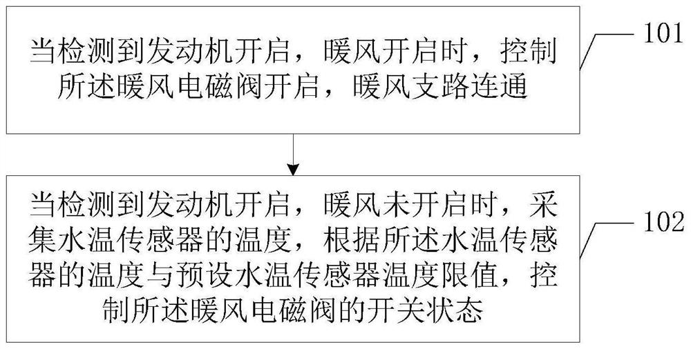
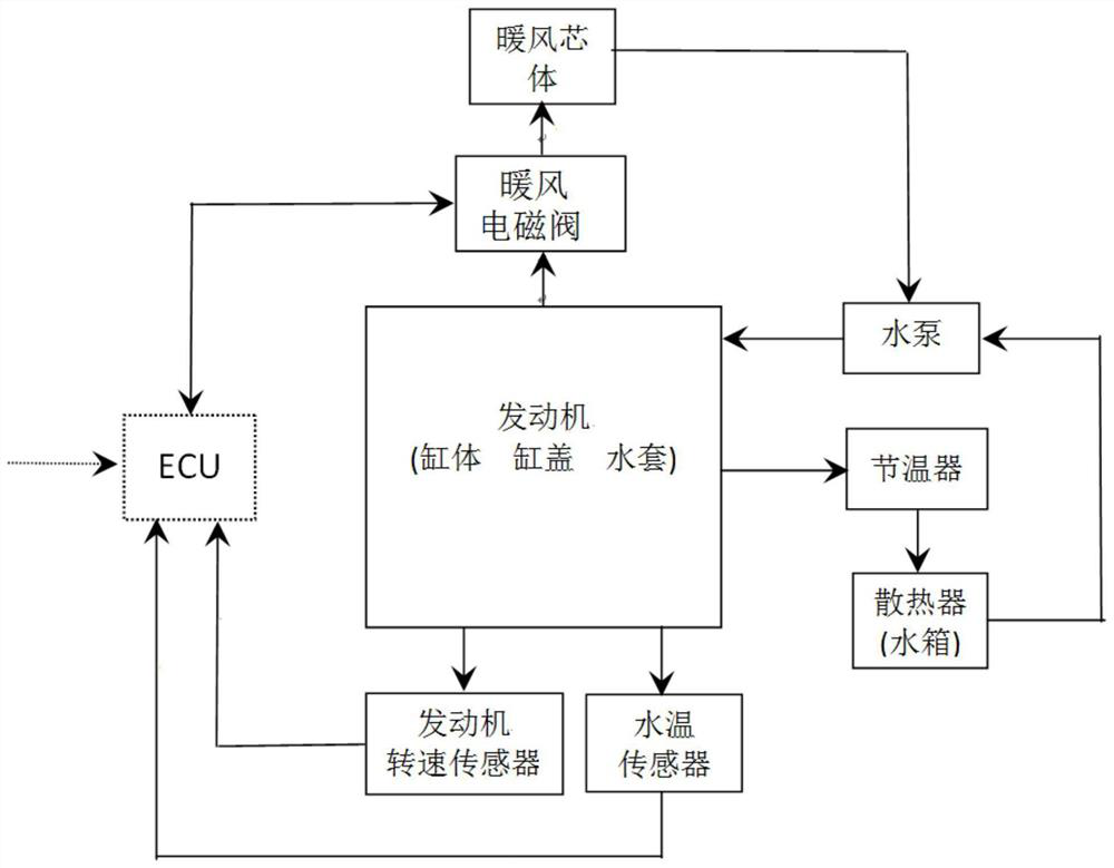
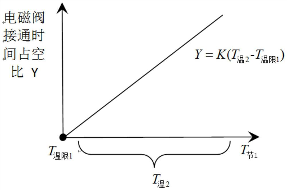
[0042] figure 1 A schematic diagram of an implementation flow of a control method for a vehicle heating system provided by an embodiment of the present invention is described in detail as follows. like figure 2 Shown is a vehic...


PUM


Abstract

The invention is suitable for the technical field of vehicle warm air control, and provides a control method of a vehicle warm air system and terminal device.The method comprises the steps that when it is detected that an engine is started and warm air is started, a warm air electromagnetic valve is controlled to be started, a warm air branch is controlled to be communicated, rapid warm-up is achieved, and fuel consumption is reduced; when it is detected that the engine is started and the warm air is not started, the temperature detected by the water temperature sensor is collected, and the on-off state of the warm air electromagnetic valve is controlled according to the temperature of the water temperature sensor and the preset temperature limit value of the water temperature sensor, so that cooling water in the engine of the vehicle is intelligently controlled to flow under different working conditions of the engine, and the cooling effect is improved. The engine can be quickly warmed or cooled, faults such as cylinder scoring or scrapping of the engine are prevented, the service life of the engine is prolonged, and user experience is improved.

Description

technical field [0001] The invention belongs to the technical field of vehicle warm air control, and in particular relates to a control method and terminal equipment of a vehicle warm air system. Background technique [0002] At present, as long as the engine of the vehicle is running, the water in the heater branch of the vehicle takes water from the engine, flows through the heater core, and then enters the water pump of the engine again, and so on. [0003] During the engine warm-up process, the water pump drives the engine coolant from the internal water jacket of the engine to return to the water pump through the heater core. Because the circulating water in the heater branch continues to take away the engine heat, the engine coolant temperature rises slowly, resulting in warm-up. long time. [0004] Under the high-speed and high-load operating conditions of the engine, the engine generates a large amount of heat, and a large amount of cooling water needs to flow throu...

Claims


Application Information

Patent Timeline
Patent Type & Authority Applications(China)
IPC IPC(8): B60H1/04B60H1/06
CPCB60H1/04B60H1/06
Inventor 胡洪涛魏永强曹永伟杨颖
Owner GREAT WALL MOTOR CO LTD
Learn More