
Impeller assembly for low-loss centrifugal fan and fan thereof

A centrifugal fan and low-loss technology, applied to machines/engines, components of pumping devices for elastic fluids, pump components, etc., can solve problems such as easy to generate loud noise, stability impact, equipment vibration, etc., to achieve Good thermal deformation resistance, reduced flow resistance, and the effect of suppressing turbulence

Pending Publication Date: 2022-07-12
浙江尚扬通风设备有限公司
View PDF22 Cites 0 Cited by
  • Summary
  • Abstract
  • Description
  • Claims
  • Application Information

AI Technical Summary

Problems solved by technology

When it reaches the pipe network, because the force is not reduced immediately, compared with the force at the output position, it has a certain influence on the force in the pipe network, causing the gas in the pipe network to flow back into the centrifugal fan, because the low-frequency and high-amplitude The form of vibration, and at the same time, the vibration of the airflow occurs regularly during the operation of the equipment, which easily produces loud noises, causing the equipment to vibrate, which seriously affects its stability, and then causes the surge phenomenon

Method used


Image

  • Impeller assembly for low-loss centrifugal fan and fan thereof
  • Impeller assembly for low-loss centrifugal fan and fan thereof
  • Impeller assembly for low-loss centrifugal fan and fan thereof

Examples


Embodiment 1

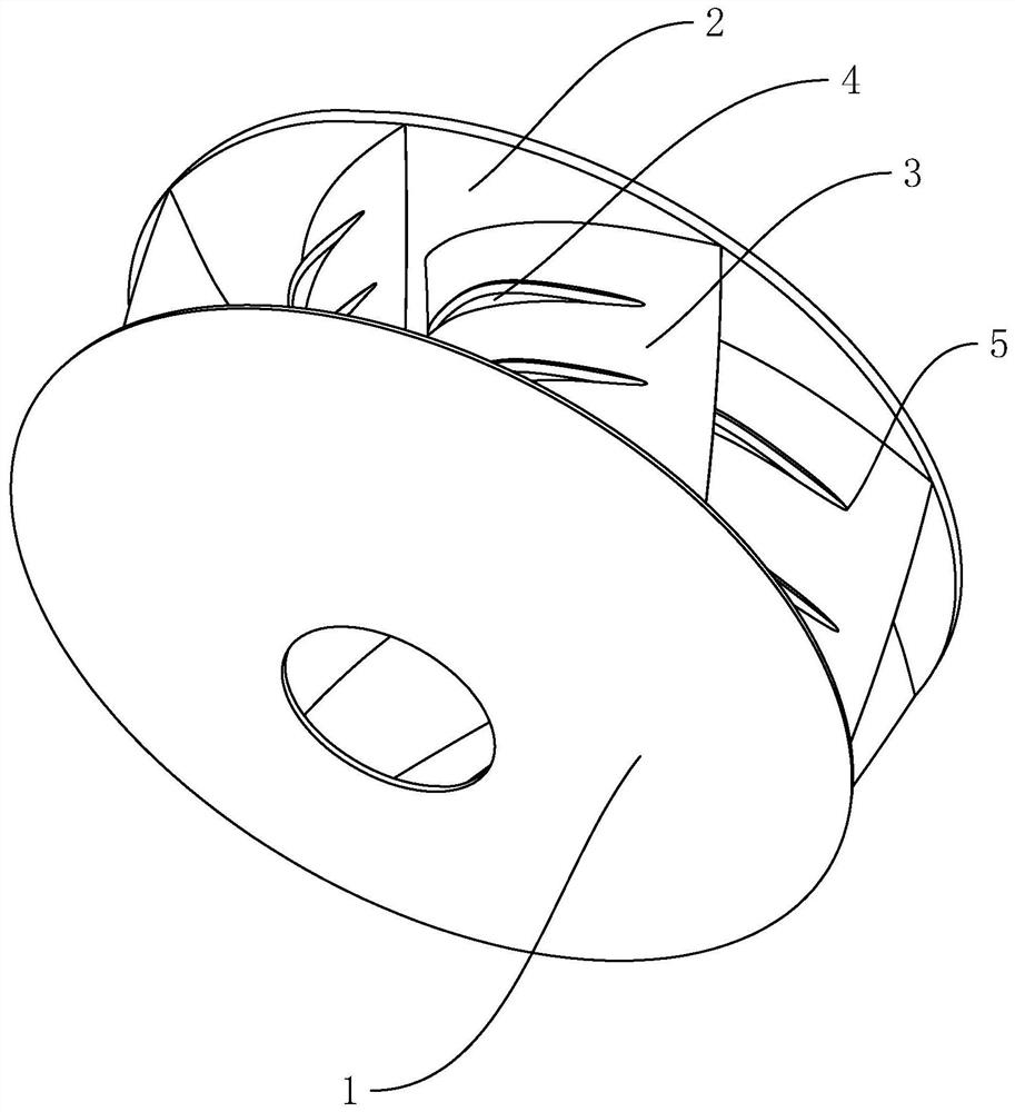
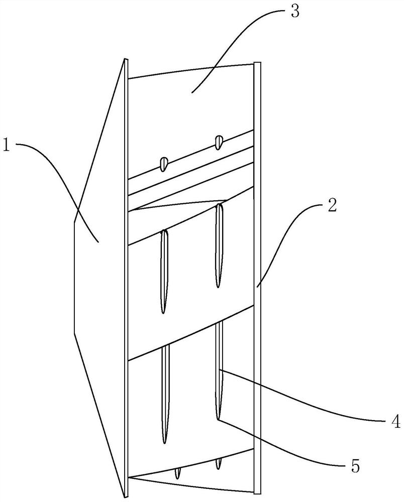
[0037]Embodiment 1: An impeller assembly for a low-loss centrifugal fan, comprising a front cover 1, a rear cover 2, and a plurality of backward blades 3 located between the front cover 1 and the rear cover 2, and the plurality of backward blades 3 are The annular array is distributed between the front cover plate 1 and the rear cover plate 2, and the end of the rearward blade 3 facing the center of the annular array of the plurality of rearward blades 3 is provided with an arc portion 6, and the arc-shaped concave surface of the arc portion 6 faces the edge of the rearward blade 3. The rearward vane 3 is arranged in the direction of the end, and the array center of the rearward vane 3 is concentric with the front cover 1 and the rear cover 2. The rearward vane 3 is an arc structure. The fins 4 are arranged in the arc length direction of the blade 3. The fins 4 are used to suppress turbulent bursts. In this embodiment, the front cover 1, the rear cover 2 and the rearward blade ...

Embodiment 2

[0041] Embodiment 2: a low-loss centrifugal fan, further comprising a volute for accommodating the impeller assembly, the volute is provided with an air inlet and an air outlet 7, and the guide baffle 13 located at the air outlet 7 is fixedly connected in the volute , the guide baffle 13 is obliquely arranged on the air outlet 7 so that the diameter of the air outlet 7 gradually decreases, the guide baffle 13 and the inner wall of the volute are filled with sound-absorbing filling particles, and the volute is detachably connected to the air inlet. The current collector 8 has a hollow trumpet-shaped structure, and an elastic flange 9 is formed at one end of the current collector 8 located in the volute. It is arranged coaxially with the inlet of the front cover 1, and a buffer assembly is provided between the collector 8 and the inner wall of the volute. A cone-shaped structure, the end of the support portion 10 facing the front cover 1 is provided with a ring portion 12 that i...


PUM


Abstract

The invention discloses an impeller assembly for a low-loss centrifugal fan and the fan thereof, relates to ventilation equipment, and aims to solve the problems that air flows back to the centrifugal fan and airflow vibration occurs regularly in the running process of the equipment, so that the equipment vibrates and surges are caused, and the service life of the equipment is prolonged. According to the technical scheme, the impeller is characterized by comprising a front cover plate, a rear cover plate and a plurality of backward blades located between the front cover plate and the rear cover plate, each backward blade is of an arc structure, a plurality of fin parts arranged in the arc length direction of the backward blades are arranged on the arc convex face of each backward blade, and the fin parts are used for restraining turbulence burst. The noise reduction filling particles are arranged, noise reduction can be carried out on the air inlet and the air outlet of the fan, the running noise of the centrifugal fan is reduced, the surge phenomenon of the centrifugal fan can be restrained by combining the fin parts formed on the surfaces of the backward blades in the impeller assembly, meanwhile, the airflow backflow phenomenon is eliminated, and the working efficiency of the centrifugal fan is improved.

Description

technical field [0001] The present invention relates to ventilation equipment, more particularly, it relates to an impeller assembly for a low-loss centrifugal fan and a fan thereof. Background technique [0002] The centrifugal fan is a machine that relies on the input mechanical energy to increase the gas pressure and discharge the gas. It is a driven fluid machine. Centrifugal fans are widely used in ventilation, dust removal and cooling of factories, mines, tunnels, cooling towers, vehicles, ships and buildings, as well as ventilation and induced air in boilers and industrial furnaces; cooling and air conditioning equipment in air conditioning equipment and household appliances. Ventilation; drying and selection of grain; air source of wind tunnel and inflation and propulsion of hovercraft, etc. [0003] The centrifugal fan is based on the principle of converting kinetic energy into potential energy. The high-speed rotating impeller accelerates the gas, then decelerates...

Claims


Application Information

Patent Timeline
Patent Type & Authority Applications(China)
IPC IPC(8): F04D29/28F04D29/30F04D29/44F04D29/66
CPCF04D29/281F04D29/30F04D29/441F04D29/664F04D29/667
Inventor 顾鉴顾炜
Owner 浙江尚扬通风设备有限公司
Learn More