Novel salinity difference energy storage and power device

A power device and salt difference technology, applied in the field of salt difference energy storage, can solve the problems of environmental pollution, high cost of energy storage devices, large consumption of non-renewable resources, etc., and achieve huge application potential, low power generation cost, and simple structure Effect

Pending Publication Date: 2022-07-12
HEILONGJIANG UNIV
View PDF0 Cites 0 Cited by
  • Summary
  • Abstract
  • Description
  • Claims
  • Application Information

AI Technical Summary

Problems solved by technology

[0002] With the rapid development of the global economy, people's demand for energy is increasing. Traditional fossil energy has problems such as large consumption of non-renewable resources and serious environmental pollution. Water conservancy, wind power and other new energy technologies are affected by natural environment conditions, regional adaptability, Restrictions on factors such as operational stability and storage safety
[0003] At the river estuary of each city, there is a natural pressure difference in this place. How to make full use of this part of the pressure difference and convert it into electrical energy is a very valuable thing; for this kind of clean energy, a lot of energy is actually needed. However, the cost of traditional energy storage devices is high, so it is urgent to develop efficient and environmentally friendly power generation methods, improve resource utilization, and strengthen the recycling of renewable energy to solve the increasingly prominent energy economy and sustainable development of the ecological environment. question

Method used


Image

  • Novel salinity difference energy storage and power device
  • Novel salinity difference energy storage and power device
  • Novel salinity difference energy storage and power device

Examples


Embodiment Construction

[0032] The technical solutions in the embodiments of the present invention will be clearly and completely described below with reference to the accompanying drawings in the embodiments of the present invention. It should be noted that the embodiments of the present invention and the features of the embodiments may be combined with each other without conflict, and the described embodiments are only a part of the embodiments of the present invention, rather than all the embodiments.

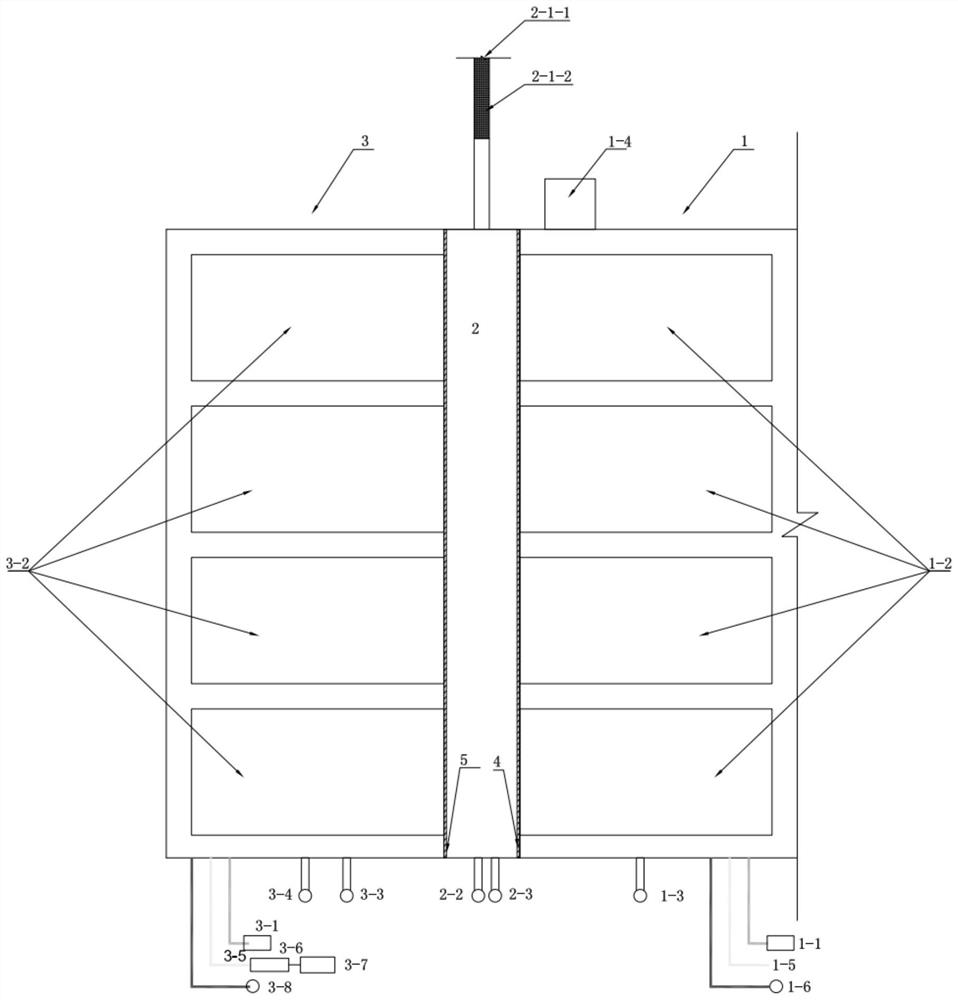
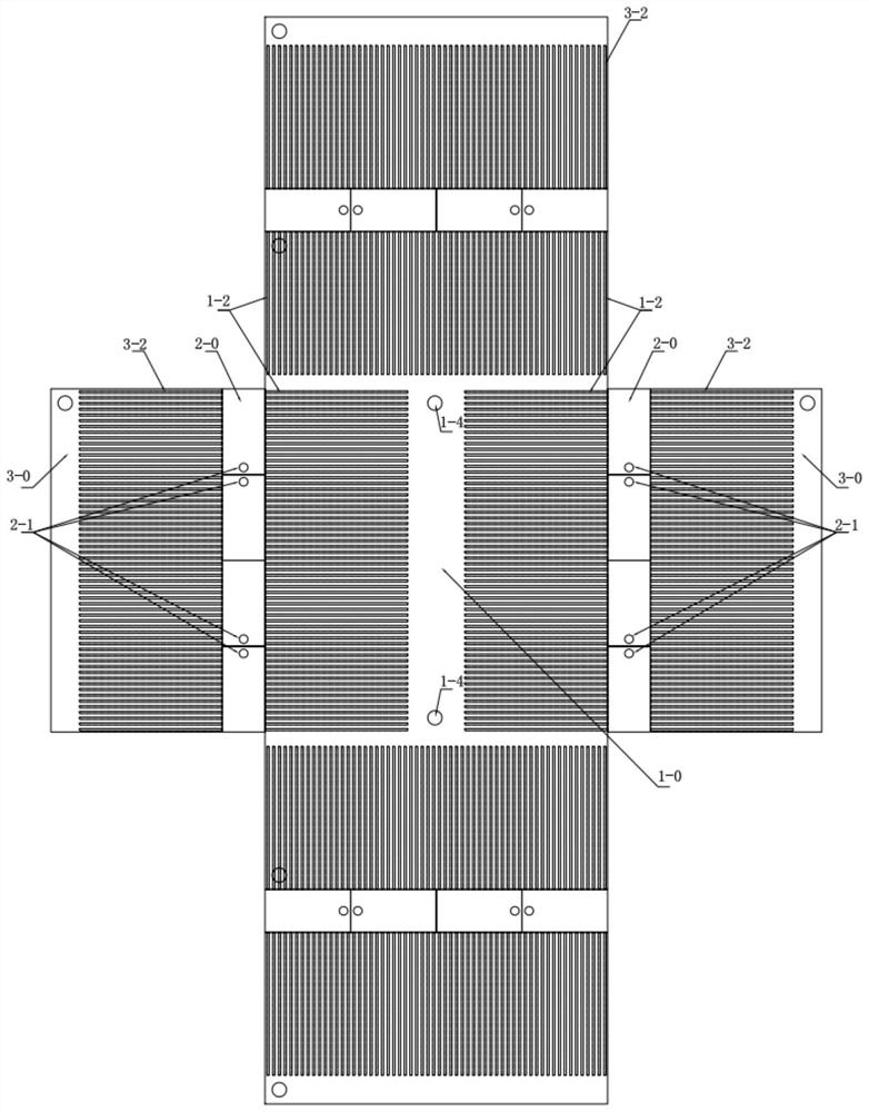
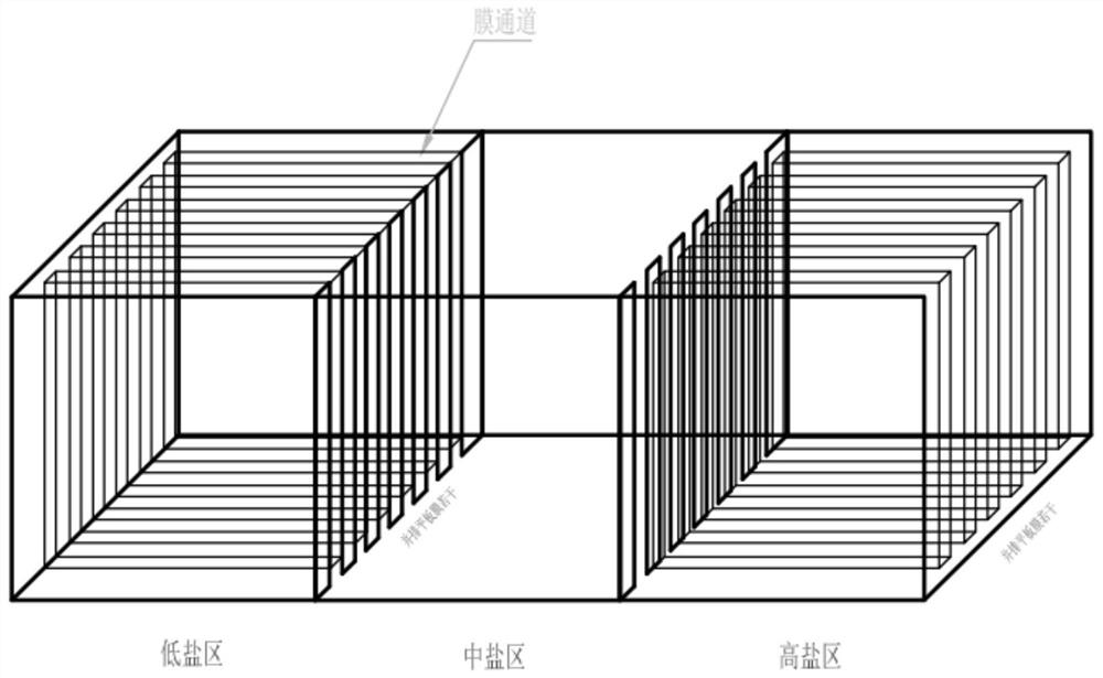
[0033] like Figure 1-Figure 4 As shown in the figure, a new type of salt difference energy storage and power device includes a fresh water zone 1, a medium salt zone 2, a high salt zone 3, and a first reciprocating device for switching salt solutions of different concentrations in the fresh water zone 1 and the middle salt zone 2 The linkage gate device 4 and the second reciprocating linkage gate 5 device for switching the salt solutions of different concentrations between the middle salt zone 2 a...


PUM


Abstract

The invention provides a novel salinity difference energy storage and power device, and belongs to the technical field of salinity difference energy. The problem of energy utilization in areas such as river estuaries, ships, submarines and salt lakes is solved. The system comprises a fresh water area, a medium salt area, a high salt area, a first reciprocating linkage gate device for switching salt solutions with different concentrations between the fresh water area and the medium salt area, and a second reciprocating linkage gate device for switching salt solutions with different concentrations between the medium salt area and the high salt area, the fresh water area comprises a fresh water tank and a fresh water supply system, the medium salt area comprises a medium salt tank and an engine acting device, the high salt area comprises a high salt tank, a high salt water supply system and a high salt flat permeable membrane, and the two reciprocating linkage gate devices are identical in structure and are pneumatic gates. Salt solutions with different concentrations in the three areas are switched through switches of the two reciprocating linkage gate devices to form pressure difference to drive an engine acting device to output power. The invention provides a green energy source, and the whole system is simple in structure, free of chemical fuel combustion and low in power generation cost.

Description

technical field [0001] The invention belongs to the technical field of salt difference energy storage, and in particular relates to a novel salt difference energy storage and power device. Background technique [0002] With the rapid development of the global economy, people's demand for energy is increasing day by day. Traditional fossil energy has problems such as large consumption of non-renewable resources and serious environmental pollution. Water conservancy, wind power and other new energy technologies are affected by natural environment conditions, regional adaptability, Operational stability, storage safety and other factors. [0003] At the mouth of the river in each city, there is a natural pressure difference in this place. How to make full use of this part of the pressure difference and convert it into electricity is a very valuable thing; for this clean energy, a large amount of energy is actually needed. However, the cost of traditional energy storage devices...

Claims


Application Information

Patent Timeline
IPC IPC(8): F03G7/00
CPCY02E10/30
Inventor 许铁夫侯音
Owner HEILONGJIANG UNIV
Why Eureka
Try Eureka