Anti-interruption feeding system for dry denitration conveying equipment

A technology of conveying equipment and feeding system, which is applied in the field of anti-interruption feeding system for dry denitrification conveying equipment, which can solve the problems of affecting material conveying, accumulation on the pipe wall, and affecting the normal progress of chemical reactions, etc., to expand the distribution area Domain, the effect of improving efficiency

Inactive Publication Date: 2022-07-12
甘肃泰聚环保科技有限公司
View PDF6 Cites 1 Cited by
  • Summary
  • Abstract
  • Description
  • Claims
  • Application Information

AI Technical Summary

Problems solved by technology

[0002] In the existing dry denitrification process, the material in the feeding equipment needs to be transported to the reaction furnace for reaction. During the transport process, the accelerator needs to provide wind load to accelerate the material so that the material can be transported into the reaction furnace. However, due to the limitation of the structure of the conventional accelerator, the mixing of the conveying wind and the material is not sufficient, and the material will accumulate on the pipe wall, which will cause the pipe to be blocked and affect the transportation of the material, resulting in the inability of the material in the furnace to be transported in time. , affect the normal progress of the chemical reaction, so the anti-interruption feeding system for dry denitrification conveying equipment is designed here to solve the above problems

Method used


Image

  • Anti-interruption feeding system for dry denitration conveying equipment
  • Anti-interruption feeding system for dry denitration conveying equipment
  • Anti-interruption feeding system for dry denitration conveying equipment

Examples


Embodiment 1

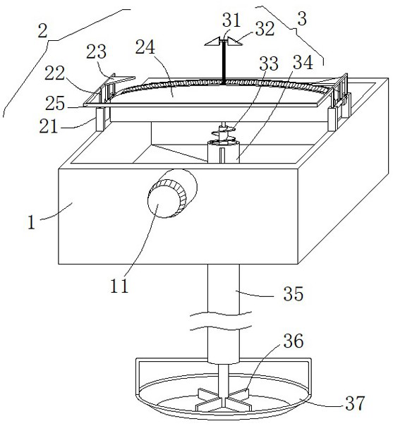
[0033] see figure 1 , figure 2 , Image 6 , Figure 7 and Figure 9 , This embodiment provides an anti-interruption feeding system for dry denitrification conveying equipment, including a hopper 1, a spreading mechanism 3 for introducing the materials in the hopper 1 into the furnace, and a guiding mechanism 2 for evenly swinging and spreading the material by the auxiliary spreading mechanism 3, The hopper 1 is used to hold the materials to be exported. The material in the hopper 1 is introduced into the furnace by the spreading mechanism 3. The guide mechanism 2 assists the spreading mechanism 3 to evenly sway and spread the material, and at the same time, it can also realize the expansion of the distribution area of ​​the material. Improve the chemical reaction efficiency and improve the denitration efficiency.

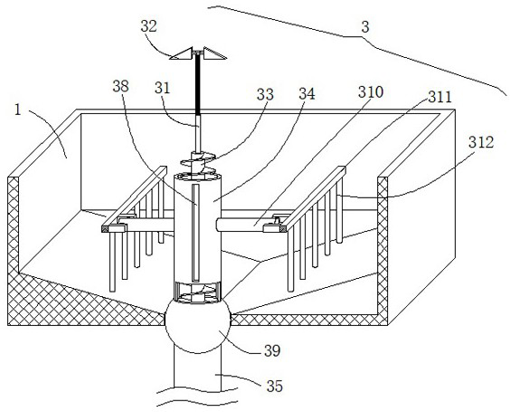
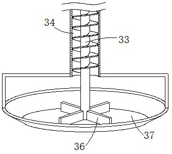
[0034]The material spreading mechanism 3 includes a first material guide pipe 34 and a second material guide pipe 35. A hollow spherical block 39 is fixedly co...

Embodiment 2

[0043] see figure 1 , Figure 5 , Image 6 , Figure 7 , Figure 8 and Figure 9 , made further improvements on the basis of Example 1:

[0044] In order to facilitate the adjustment of the position of the guide seat 24 forward and backward on the hopper 1, the guide mechanism 2 includes two sets of support blocks 21, the two support blocks 21 are a set, and the two sets of support blocks 21 are respectively arranged on both sides of the upper end of the hopper 1, and the same A pin shaft 29 is rotatably provided between the two supporting blocks 21 of the group. Both ends of the guide seat 24 are fixedly provided with a sliding block 26 slidably inserted with the pin shaft 29. 21 on the pin 29.

[0045] In addition, by sliding the slider 26 along the outer wall of the pin shaft 29 to adjust the position, the guide seat 24 can be adjusted back and forth. Alternately engage with the tooth slots 313 of the rocking rod 31 to ensure that when the rocking rod 31 swings left ...

Embodiment 3

[0050] see figure 1 , figure 2 and Figure 4 , made further improvements on the basis of Example 2:

[0051] In order to realize the automatic and even material spreading operation, the outer wall of the hopper 1 is provided with a transmission member 11 capable of swinging the rocking rod 31 back and forth in the fan-shaped guide hole, and the transmission member 11 is used to drive the rocking rod 31 to swing back and forth in the fan-shaped guide hole, so as to achieve uniform continuous swing. Effective spreading operation.

[0052] The transmission member 11 is preferably a motor, and the power shaft of the motor rotates and extends to the interior of the hopper 1, and is fixedly connected with a Z-shaped lever 12, the other end of the Z-shaped lever 12 is fixed with a plug-in rod 13, and the first material guide tube 34 The outer wall is provided with axially distributed guide grooves 38, the plug-in rod 13 is slidably connected with the guide groove 38, the motor pr...


PUM


Abstract

The invention discloses an anti-interruption feeding system for dry denitration conveying equipment, and relates to the technical field of dry denitration feeding, the anti-interruption feeding system comprises a hopper, a material scattering mechanism for guiding materials in the hopper into a hearth and a guide mechanism for assisting the material scattering mechanism to uniformly swing and scatter the materials, and the material scattering mechanism comprises a first material guide pipe and a second material guide pipe; a hollow spherical block is fixedly connected between the first material guide pipe and the second material guide pipe, a swing rod penetrates through a fan-shaped guide hole in a sliding mode, and the swing rod is limited by the fan-shaped guide hole and can only swing in the fan-shaped guide hole in a reciprocating mode, so that materials guided out of the second material guide pipe are evenly sprayed. Tooth blocks distributed in a fan-shaped structure are arranged on the side walls of the front side and the rear side of the interior of the fan-shaped guide hole, and tooth grooves meshed with the tooth blocks are formed in the outer wall of the swing rod. Materials in the hopper are guided into the hearth through the material scattering mechanism, the material scattering mechanism is assisted by the guide mechanism to evenly swing and scatter the materials, meanwhile, the distribution area of the materials can be enlarged, the chemical reaction efficiency is improved, and the denitration efficiency is improved.

Description

technical field [0001] The invention relates to the technical field of dry denitration feeding, in particular to an anti-interruption feeding system for dry denitration conveying equipment. Background technique [0002] In the existing dry denitration process, the materials in the feeding equipment need to be transported to the reaction furnace for reaction. During the transportation process, the air load needs to be provided by the accelerator to accelerate the materials, so that the materials can be transported to the reaction furnace. The reaction is carried out, but due to the limitation of the structure of the conventional accelerator, the mixing of the conveying air and the material is not sufficient, and the material will accumulate on the pipe wall, which will cause the pipe to be blocked, affect the transportation of the material, and cause the material in the furnace to be unable to be transported in time. , affecting the normal progress of the chemical reaction, s...

Claims


Application Information

Patent Timeline
IPC IPC(8): B01J4/00B65D88/64B01D53/81B01D53/56
CPCB01J4/007B65D88/64B01D53/81B01D53/56
Inventor 王杰祁晓锋
Owner 甘肃泰聚环保科技有限公司
Why Eureka
Try Eureka