
Power storage battery

A power storage and battery technology, applied in the direction of batteries, secondary batteries, battery pack components, etc.

Pending Publication Date: 2022-07-08
FAURECIA SYST DECHAPPEMENT
View PDF1 Cites 0 Cited by
  • Summary
  • Abstract
  • Description
  • Claims
  • Application Information

AI Technical Summary

Problems solved by technology

[0009] However, in order to omit such a holding device, a number of constraints need to be met

Method used


Image

  • Power storage battery
  • Power storage battery
  • Power storage battery

Examples


Embodiment Construction

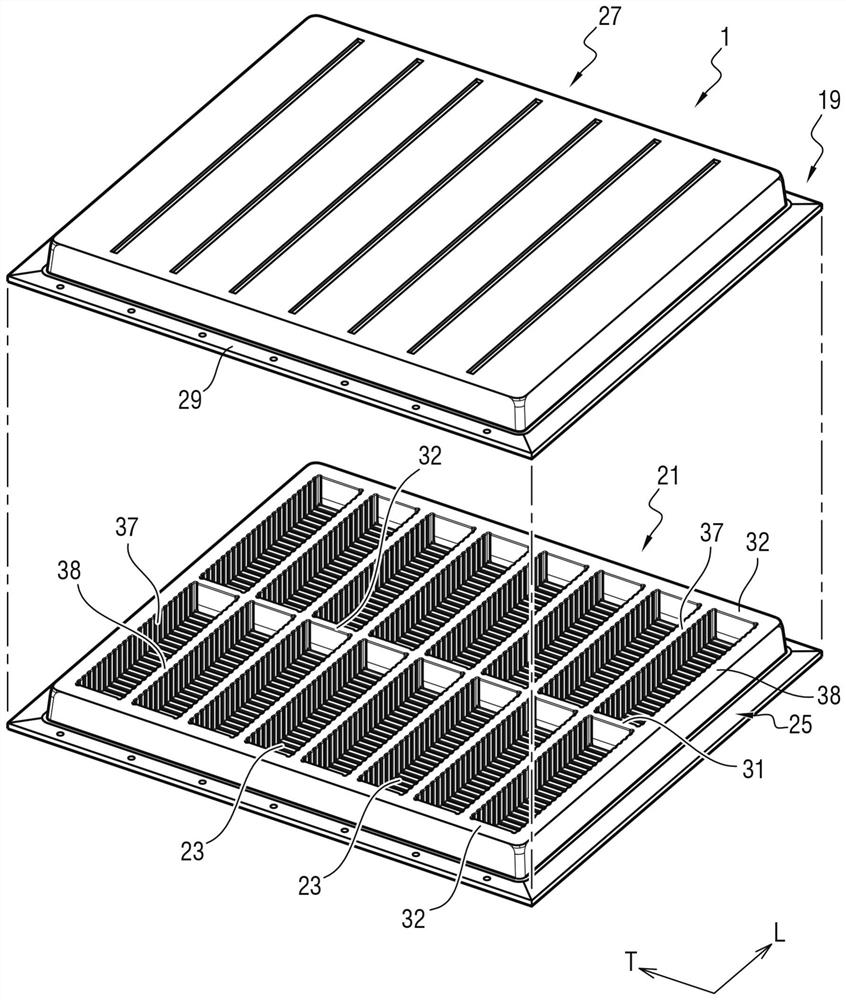
[0050] Figure 1 to Figure 4 The power battery 1 shown in is used to equip a vehicle, usually a motor vehicle, such as a car, bus or truck.

[0051] The vehicle is, for example, a vehicle propelled by an electric motor, which is powered by an electric battery. As a variant, the vehicle is of the hybrid type and thus includes a heat engine and an electric motor powered by an electric battery. According to yet another variant, the vehicle is propelled by a heat engine and the electrical battery is arranged to supply power to other equipment of the vehicle, such as the starter, lights and the like.

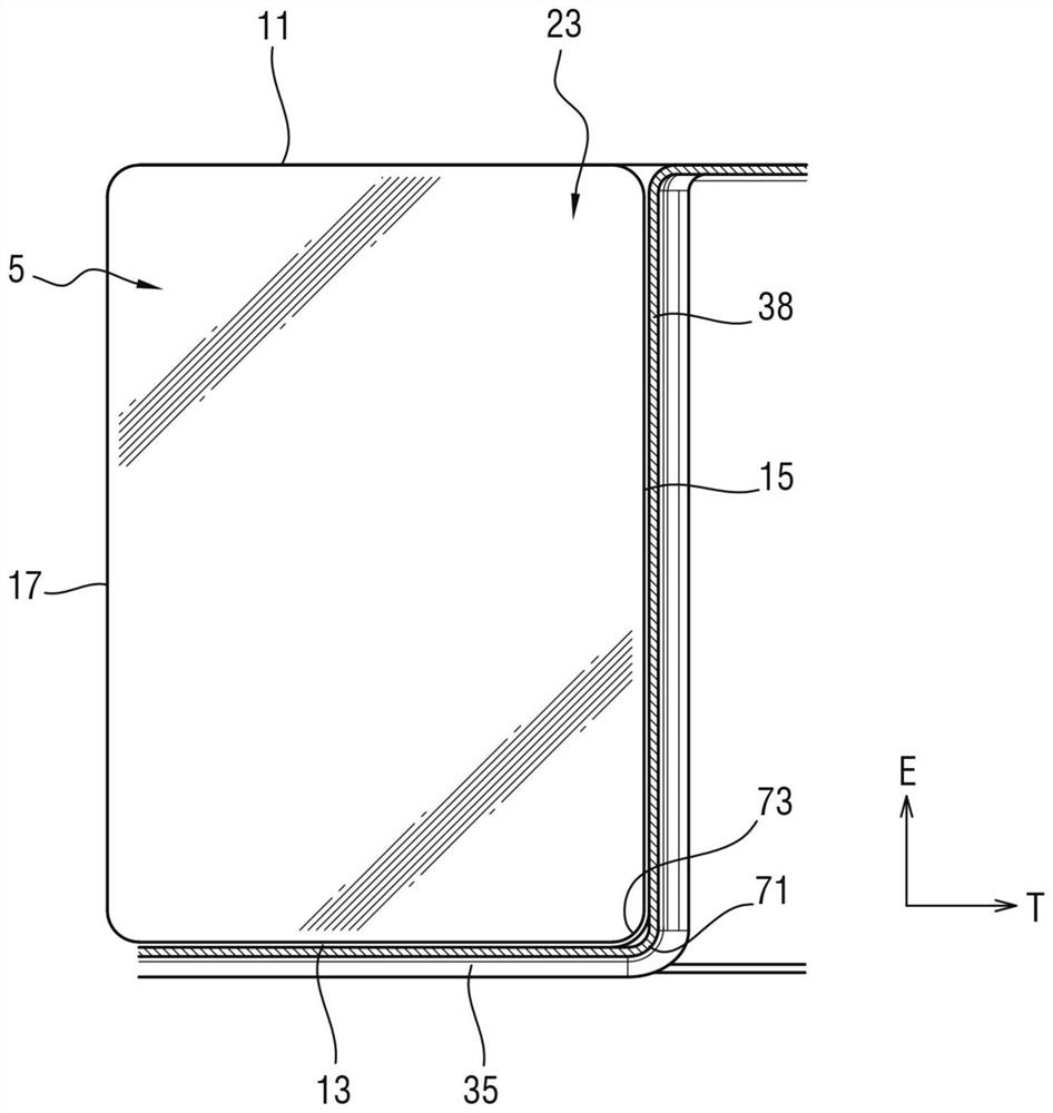
[0052] The power storage battery 1 includes at least one module 3 ( Figure 4 ), the module includes a number N of power storage battery cells 5 .

[0053] The number of modules 3 of the battery is a function of the power storage capacity of the battery 1 . In the example shown, the battery has sixteen modules 3 . However, the battery may have more or less than sixteen modules.

...


PUM


Abstract

The invention provides a power storage battery (1) comprising at least one module (3) comprising power storage battery cells (5), each power storage battery cell (5) having a nominal value thickness E0, and at least one compartment (23) for receiving the at least one module (3); at least one of the transverse walls (31, 32) of the compartment is made of an elastic material; when the module (3) is engaged in the compartment (23), the transverse walls (31, 32) exert a compressive stress on the module (3) adapted to maintain the power storage cell (5) substantially at its nominal thickness E0.

Description

technical field [0001] The present invention relates generally to batteries for electrical power storage, in particular batteries for motor vehicles. Background technique [0002] Application number FR 20 07331 discloses an electricity storage battery, the cells of which are cooled by direct contact with a dielectric liquid. [0003] The use of a dielectric liquid allows direct cooling of live components without compromising the operation of these components, since the conductivity of the liquid can be considered to be zero. This cooling is very efficient and allows to obtain good exchange densities. It also allows cooling of large surfaces. [0004] In contrast, indirect contact cooling systems typically do not allow cooling of the entire surface of the heat-generating component. In such systems, only the most accessible parts of the components are cooled. This inevitably leads to undesired temperature gradients. [0005] In particular, in air circulation cooling syste...

Claims


Application Information

Patent Timeline
IPC IPC(8): H01M50/204H01M50/233H01M50/244H01M50/289
CPCH01M50/204H01M50/244H01M50/233H01M50/289H01M10/0481H01M10/6567H01M10/6561H01M50/209H01M50/227H01M50/231H01M50/249H01M50/264H01M10/613H01M10/625H01M10/647Y02E60/10H01M2220/20
Inventor 弗雷德里克·格雷贝尔
Owner FAURECIA SYST DECHAPPEMENT
Learn More