
Well mouth centering device of workover rig and well mouth centering method of elevator of workover rig

A technology of centering device and workover rig, which is used in earth-moving drilling, drilling equipment, transportation and packaging, etc. It can solve the problems of not achieving fast and accurate centering, affecting the construction progress, and not having level adjustment, etc., so as to improve the operation. The effect of construction efficiency, avoiding wear and wellhead hanging, and eliminating hidden dangers of accidents

Pending Publication Date: 2022-07-08
CHINA PETROLEUM & CHEM CORP +1
View PDF0 Cites 0 Cited by
  • Summary
  • Abstract
  • Description
  • Claims
  • Application Information

AI Technical Summary

Problems solved by technology

However, the existing hydraulically supported jack legs only have the functions of carrying and adjusting up and down, and can only adjust the height of the working machine, without the function of level adjustment
[0006] The in-place alignment methods of the workover rig, including the tape measure method or the tripod auxiliary reference method, cannot fail to achieve fast and accurate alignment, which affects the construction progress. Wellhead

Method used


Image

  • Well mouth centering device of workover rig and well mouth centering method of elevator of workover rig
  • Well mouth centering device of workover rig and well mouth centering method of elevator of workover rig
  • Well mouth centering device of workover rig and well mouth centering method of elevator of workover rig

Examples


Embodiment Construction

[0038] In the following description of the present invention, the orientation or positional relationship indicated by the terms "upper", "lower", "front", "rear", "left", "right", "inner", "outer", etc. is based on the attached The orientation or positional relationship shown in the figures is only for the convenience of describing the present invention and simplifying the description, and does not mean that the device must have a specific orientation.

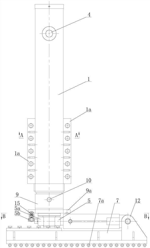
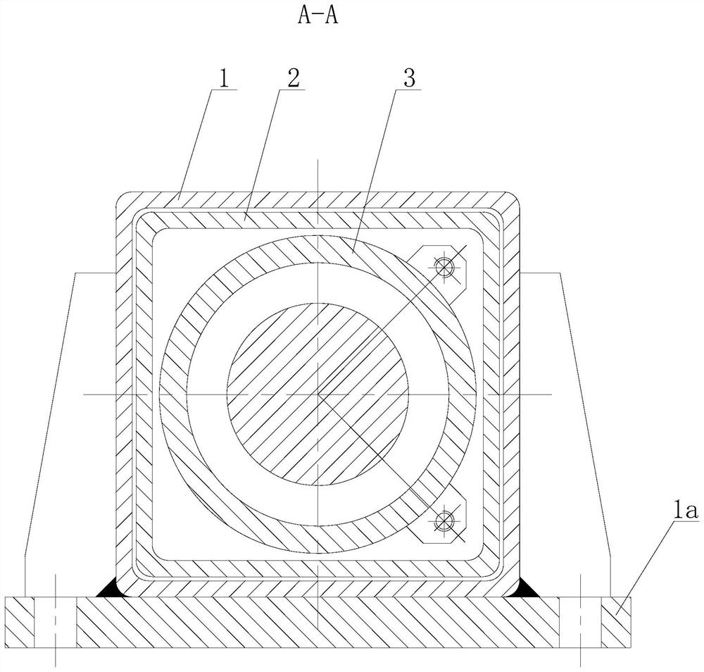
[0039] like Figure 1 to Figure 5 As shown in the figure, the wellhead centering device of the workover rig of the present invention comprises an outer leg housing 1 connected below the four support points of the workover rig, and the outer wall of each leg outer casing 1 is welded with flanges of the outer wall of the outrigger respectively. 1a, the outer shell flange 1a of the outrigger is fixedly connected with the chassis of the workover rig through bolts. The inner cavity of the outrigger outer casing 1 is respectively p...


PUM


Abstract

The invention discloses a workover rig wellhead centering device and a workover rig elevator wellhead centering method.The workover rig wellhead centering device is characterized in that a supporting leg inner shell is arranged in a supporting leg outer shell, a supporting leg oil cylinder is fixed in the inner shell, an upper piston rod of the supporting leg oil cylinder is hinged to the upper end of the supporting leg outer shell, and the lower end of a supporting leg of the supporting leg oil cylinder is connected to the upper end of a translation sliding column; the periphery of the middle section of the translation sliding column is sleeved with a shackle, and the bottom of the translation sliding column is supported in a sliding groove of the translation sliding seat; a shackle hinge lug on the outer wall of the shackle is hinged to the end of a piston rod of a translation oil cylinder, and a cylinder body of the translation oil cylinder is hinged to a translation oil cylinder hinge seat at one end of the translation sliding seat. The translation sliding seats are rotated to enable the direction of the workover rig to be translated to be aligned with a wellhead, then the piston rods of the translation oil cylinders contract, the supporting legs are put down, a foundation is compacted, the piston rods of the translation oil cylinders stretch out synchronously, and the translation sliding columns are pushed to bear the workover rig chassis to slide towards the wellhead until centering is achieved. According to the invention, the elevator and the center of a wellhead can be quickly and accurately centered.

Description

technical field [0001] The invention relates to a workover rig, in particular to a wellhead centering device for a workover rig; the invention also relates to a wellhead centering method for an elevator of a workover rig, belonging to the technical field of workover operations in oil fields. Background technique [0002] Workover rigs are often used in oilfield workover operations. The derrick of the workover rig stands at the wellhead. The top of the derrick is provided with a top pulley. The wire rope drum is fixed on the chassis of the car. Elevator, the elevator is lifted and lowered along the guide rail on the derrick, the pipe string is lifted out of the well or into the well, or the suspension tubing is docked with the downhole pipe string. [0003] The load-bearing center of the elevator should be aligned with the center of the wellhead to ensure that it will not be offset when lifting the downhole pipe string, and avoid the pipe string hanging on the wellhead. When...

Claims


Application Information

Patent Timeline
Patent Type & Authority Applications(China)
IPC IPC(8): B60S9/20E21B19/00
CPCB60S9/20E21B19/00
Inventor 朱宏雷永明陈彧吕卫祥孙建超石立黎
Owner CHINA PETROLEUM & CHEM CORP
Learn More