
Method for constructing coexistence of aerobic fungi and facultative or anaerobic microorganisms by utilizing 3D printing

An anaerobic microorganism, 3D printing technology, applied in the field of biological materials and synthetic biology, can solve the problems of artificial microorganism co-cultivation system difficulty, difficulty in maintaining different strain groups, etc., to achieve high specific surface area and improve the effect of mass transfer

Pending Publication Date: 2022-07-05
NANJING UNIV OF TECH
View PDF8 Cites 0 Cited by
  • Summary
  • Abstract
  • Description
  • Claims
  • Application Information

AI Technical Summary

Problems solved by technology

However, stable artificial microbial co-culture systems are still difficult due to the difficulty in maintaining an optimal balance between populations of different strains and the need to create specific microenvironmental conditions required by different strains.
For example, a major challenge in constructing such a bottom-up CBP system is the oxygen concentration requirement between aerobic fungi and facultative or anaerobic microorganisms

Method used


Image

  • Method for constructing coexistence of aerobic fungi and facultative or anaerobic microorganisms by utilizing 3D printing
  • Method for constructing coexistence of aerobic fungi and facultative or anaerobic microorganisms by utilizing 3D printing
  • Method for constructing coexistence of aerobic fungi and facultative or anaerobic microorganisms by utilizing 3D printing

Examples


Embodiment 1

[0039] Example 1 3D printing fence structure living material

[0040] The living material of the fence structure was printed using an extrusion-based 3D printer (EFL-BP66). First, a computer-aided system was used to design a 3D fence structure with high mass transfer, and then a 3D printing gel was prepared. The 3D printing gel is prepared as follows:

[0041] 1 vol.% overnight culture S. cerevisiae and 1 wt.% phenyl-2,4,6-trimethylbenzoyl phosphate (LAP) photoinitiator was added to 5 wt.% PVA-GMA. The dissolved solution was mixed with 2 wt.% PBA-SA at a ratio of 1:2 and then vortexed. After this, incubate on ice for 10 min to keep the gel free of air bubbles. The gel was then transferred into a syringe barrel with a volume of 5 mL and a nozzle length of 20 mm and deposited into continuous filaments at a printing speed of 50-70 mm / s. Light curing (405 nm) for 30 seconds after printing each layer. Finally, the living material of the printed fence structure was immediatel...

Embodiment 2

[0042] Example 2 Microbial visualization of biomass accumulation inside living materials

[0043] Using the above-mentioned method of 3D spatiotemporal design of living materials to print green fluorescent protein S. cerevisiae . Immediately after printing, rinse 6 times with PBS. Images of the living material were taken under a fluorescence microscope, and then the fence-structured living material was transferred to the culture medium (potassium dihydrogen phosphate: 3 g / L, ammonium sulfate: 5 g / L, magnesium sulfate heptahydrate: 0.5 g / L , uracil: 0.15 g / L, glucose: 40 g / L) for culture. Fluorescence images of living material were taken every 12 hours. Fluorescence microscopy uses the same parameters to ensure consistent fluorescence readings. Fluorescence was quantified using ImageJ, and the mean fluorescence intensity of 6 images collected at all time points for each printed sample was used as a parameter for biomass accumulation over time ( figure 2 (A)). like fig...

Embodiment 3

[0044] Example 3 3D printing living material for ethanol fermentation

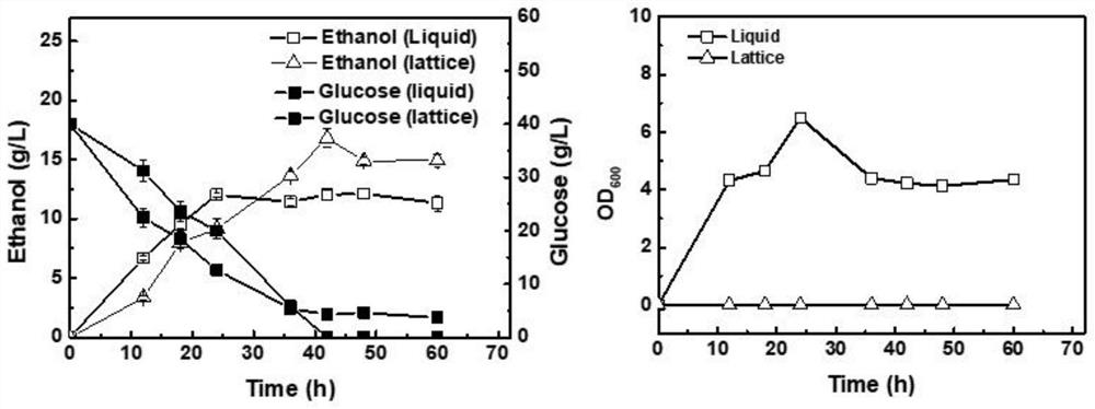
[0045] In order to verify the ability of 3D printed living materials to produce ethanol, the 3D printed fence structure living materials and free cells were used as seeds to study the fermentation kinetics. Fermentation was carried out in a 50 mL anaerobic flask containing 10 mL of fermentation medium at a temperature of 30 °C and a rotation speed of 200 rpm. The initial glucose concentration was 40 g / L. like image 3 As shown, the 3D printed barrier-structured living material Saccharomyces cerevisiae exhibited lower production efficiency within 24 h compared to suspension fermentation. It may be that the 3D printing process affects the activity of the cells, which need to adapt to the new environment at the start of fermentation. But at the late stage of fermentation, the ethanol yield in the 3D printed fence structure living material reached 16.87 g / L, which was 1.3 times that of suspension fermentati...


PUM

PropertyMeasurementUnit
diameteraaaaaaaaaa

Abstract

The invention discloses a method for constructing coexistence of aerobic fungi and facultative or anaerobic microorganisms by utilizing 3D printing, which comprises the following steps: inoculating the aerobic fungi into a fermentation culture medium, and placing a supporting material with pores on the fermentation culture medium, so that the aerobic fungi form a compact biological membrane on the supporting material; facultative or anaerobic microorganisms are made into a living body material of a fence structure through 3D printing; and putting the living body material into a fermentation culture medium, coexisting with aerobic fungi, and carrying out fermentation reaction. The invention also provides a bioreactor constructed by using the 3D printed container and the living body material. According to the invention, oxygen consumption is realized through biological membranes formed by aerobic fungi on a support material and a living body material, proper growth and production conditions are created for facultative or anaerobic microorganisms in the living body material, and a bioreactor is designed through the living body material and 3D printing equipment; the oxygen gradient is generated in the bioreactor by utilizing the oxygen consumption of aerobic bacteria, and the oxygen requirement of chemical production based on a CBP system is met.

Description

technical field [0001] The invention belongs to the field of biological materials and synthetic biology, and in particular relates to a method for constructing the coexistence of aerobic fungi and facultative or anaerobic microorganisms by using 3D printing. Background technique [0002] With the rapid development of synthetic biology, recombinant microorganisms have produced various bulk and fine chemicals. However, in the process of constructing engineered strains, factors such as the exclusivity of exogenous genes and the existence of gene silencing pathways, as well as the strict culture conditions required by the fermentation process, restrict the development of the biomanufacturing industry. By dividing metabolic modules into distinct microbial members, microbial assemblages offer a promising option for monocultures for biochemical production. A typical example is the Consolidated bioprocessing (CBP) artificial mixing system, which combines hydrolase production, ligno...

Claims


Application Information

Patent Timeline
Patent Type & Authority Applications(China)
IPC IPC(8): C12N1/14C12M1/04C12M1/00C08L29/04C08L5/04C12R1/84C12R1/885
CPCC12N1/14C12M29/00C12M25/00C08L29/04C12N2513/00C08L5/04Y02W10/10
Inventor 信丰学高豪姜岷章文明蒋羽佳姜万奎
Owner NANJING UNIV OF TECH
Learn More