
Steel coil flying shear transverse cutting device with positioning structure

A technology of positioning structure and cross-cutting device, applied in the field of flying shear cross-cutting, can solve the problems of unmaintainable, high wear, affecting cutting quality, etc., and achieve the effect of prolonging service life, avoiding blade damage and reducing wear and tear.

Inactive Publication Date: 2022-07-05
南通宏久金属制品有限公司
View PDF10 Cites 1 Cited by
  • Summary
  • Abstract
  • Description
  • Claims
  • Application Information

AI Technical Summary

Problems solved by technology

[0003] The flying shear cross-cutting machine can be used for the processing of steel coils. The steel coils are spread out and conveyed between the cutters, and the cutters are rotated to make the cutters intersect to cut off the steel coils, which can realize the fixed-length cutting of the steel coils. The following problems exist in the cutting process of the steel coil: the cutter works frequently, its wear is relatively large, and it cannot be maintained during the working process of the cutter; the position of the steel coil is easy to shift, and it cannot be stably positioned, which affects the cutting quality

Method used


Image

  • Steel coil flying shear transverse cutting device with positioning structure
  • Steel coil flying shear transverse cutting device with positioning structure
  • Steel coil flying shear transverse cutting device with positioning structure

Examples


Embodiment Construction

[0025] The technical solutions in the embodiments of the present invention will be clearly and completely described below with reference to the accompanying drawings in the embodiments of the present invention. Obviously, the described embodiments are only a part of the embodiments of the present invention, but not all of the embodiments.

[0026] In the description of the present invention, it should be understood that the terms "upper", "lower", "front", "rear", "left", "right", "top", "bottom", "inside", " The orientation or positional relationship indicated by "outside" is based on the orientation or positional relationship shown in the accompanying drawings, and is only for the convenience of describing the present invention and simplifying the description, rather than indicating or implying that the indicated device or element must have a specific orientation, so as to The specific orientation configuration and operation are therefore not to be construed as limitations of...


PUM


Abstract

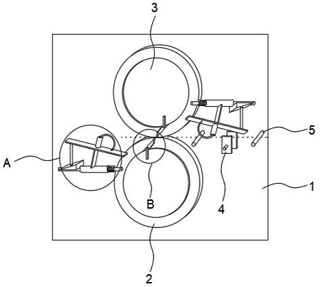
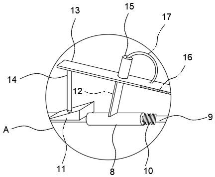
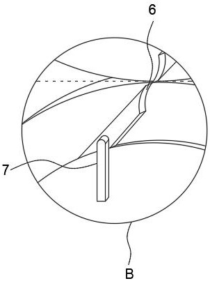
The invention discloses a steel coil flying shear transverse cutting device with a positioning structure, which comprises a rack, two meshed fluted discs are mounted on the outer wall of the rack, cutter heads are fixed on the outer walls of the fluted discs, cutters are fixed on the outer walls of the cutter heads, conveying rollers are mounted on the rack, and the conveying rollers are fixed on the rack. The outer wall of the rack is further provided with a positioning device located between the conveying rollers. And a cooling mechanism located on the outer sides of the two cutters is arranged on the outer wall of the rack, the cooling mechanism comprises a fixed pipe, a movable rod is arranged in the fixed pipe in a sliding mode, and the outer wall of the movable rod is sleeved with a telescopic spring. A steel coil is positioned through the positioning mechanism, the steel coil is prevented from deviating, the stability of transverse cutting work is guaranteed, in the reciprocating motion process of the cutter, through contact between a coating layer and the cutter, contact between cooling liquid and a cutting edge is achieved, cooling and lubricating of the cutting edge are conducted, damage to the cutting edge is avoided, and the service life is prolonged.

Description

technical field [0001] The invention relates to the technical field of flying shear cross-cutting, in particular to a steel coil flying shear cross-cutting device with a positioning structure. Background technique [0002] The steel coil is hot-pressed and cold-pressed into a coil shape. [0003] The flying shear cross-cutting machine can be used for the processing of steel coils. The rolled ends of the steel coils are transported between the cutters. The cutters are rotated to make the cutters intersect to cut the steel coils. The steel coil can be cut to a fixed length. There are the following problems in the cutting process of steel coils: the cutter frequently works, and its wear is relatively large, so it cannot be maintained during the operation of the cutter; the position of the steel coil is prone to deviation, which cannot be stably positioned, which affects the cutting quality. SUMMARY OF THE INVENTION [0004] The purpose of the present invention is to provide ...

Claims


Application Information

Patent Timeline
Patent Type & Authority Applications(China)
IPC IPC(8): B23D25/02B23D33/02B23Q11/10B21D43/08
CPCB23D25/02B23D33/02B23Q11/10B21D43/08Y02P70/10
Inventor 陈鹏
Owner 南通宏久金属制品有限公司
Learn More