Protection device of permanent magnet synchronous motor control cabinet

A permanent magnet synchronization and protective device technology, which is applied in the direction of AC motor control, substation/power distribution device casing, control system, etc., can solve problems such as difficult temperature drop, leakage, and burnout of electrical components, so as to reduce power loss and improve Lifespan, effect of preventing frostbite

Active Publication Date: 2022-07-01
TIANJIN UNIV
View PDF9 Cites 0 Cited by
  • Summary
  • Abstract
  • Description
  • Claims
  • Application Information

AI Technical Summary

Problems solved by technology

[0004] In the rainy days in summer, the humidity in the air is mostly high, and the outside humid air usually enters the inside of the control cabinet, and this moisture will not only look down on the electrical appliances inside the control cabinet, if the moisture accumulated inside the control cabinet is too If there are too many, leakage may occur; and in summer, the temperature is too high, and the temperature of the control cabinet is not easy to drop during the working process. If it is operated at high temperature for a long time, it is easy to cause the internal electrical components to burn out. In the case of low temperature in winter, the electrical components inside the control cabinet are easily damaged by freezing, resulting in failure to work normally

Method used


Image

  • Protection device of permanent magnet synchronous motor control cabinet
  • Protection device of permanent magnet synchronous motor control cabinet
  • Protection device of permanent magnet synchronous motor control cabinet

Examples


Embodiment 1

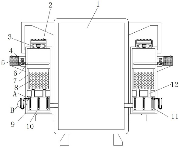
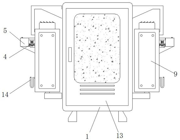
[0037] Example 1, as Figure 1-6 As shown, in the process of using the electrical cabinet in summer, the fan 3 is first started, and then the fan 3 discharges the outside air to the inside of the electrical cabinet shell 1, and then when the air passes through the cooling pipe 6, the water pump 4 starts to extract the interior of the liquid storage tank 5 The cooling liquid circulates through the cooling pipe 6, and then absorbs the temperature inside the air, and then the cooled air enters the interior of the desiccant 8, and the desiccant 8 absorbs the moisture inside the air, and finally the air enters the air through the connecting bin 11. The inside of the electrical cabinet shell 1, and the air inside the electrical cabinet shell 1 is exhausted to the outside from the exhaust port at one end of the warehouse door 13, so as to ventilate the inside of the electrical cabinet shell 1.

Embodiment 2

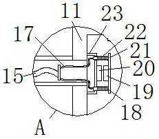
[0038] Example 2, as Figure 1-5As shown in the figure, when it is in winter, the U-shaped pipe 14 is cooled under the influence of the external cold air. Since the interior of the U-shaped pipe 14 is in a sealed state, the air on the left side of the U-shaped pipe 14 shrinks when cooled, so that the U-shaped pipe 14 is in a sealed state. The pressure on the left side inside the shaped tube 14 becomes smaller, which in turn drives the liquid level on the left side to rise. At this time, the wooden floating plate 16 on the right side moves down with the liquid level and pulls the connecting rope A15, and then the connecting rope A15 is pulled by the connecting rope B17. Two sets of sliding rods 18 make the spring 22 compress, and at the same time, the contact piece A19 and the contact piece B20 are in contact, so that the circuit is connected to start the heating tube 10, and then the heating tube 10 heats the interior of the connection chamber 11. When the air flows from the co...


PUM


Abstract

The invention discloses a protection device for a permanent magnet synchronous motor control cabinet, and the device comprises an electric appliance cabinet housing, the two sides of the electric appliance cabinet housing are symmetrically provided with installation cabins, the top of one side of each installation cabin is provided with a cooling assembly, the middle of the interior of each installation cabin is provided with a prevention groove, and the interior of each prevention groove is provided with a drying agent. Breather pipes are symmetrically arranged on the two sides of the bottom of the drying agent; under the action of the fan bin and the fan, the interior of the electric appliance cabinet shell can be ventilated, and the passing air can be dried under the action of the prevention groove and the drying agent, so that the interior of the control cabinet can be kept dry for a long time, and the situation that the work of the control cabinet is affected due to the entrance of moisture is effectively prevented; and the introduced air can be cooled under the cooperation of the water pump, the liquid storage bin and the cooling pipe, so that the temperature in the control cabinet is effectively ensured to be in a normal state in summer, and the service life of the control cabinet is prolonged.

Description

technical field [0001] The invention relates to the technical field of control cabinet protection devices, in particular to a protection device of a permanent magnet synchronous motor control cabinet. Background technique [0002] The control cabinet is to assemble switchgear, measuring instruments, protective appliances and auxiliary equipment in a closed or semi-closed metal cabinet or on the screen according to the electrical wiring requirements. The safety of the equipment and surrounding equipment, the circuit can be turned on or off with the help of manual or automatic switches during normal operation, and the circuit can be cut off or alarmed with the help of protective appliances during fault or abnormal operation. Some electrical parameters are adjusted to prompt or signal deviations from the normal working state, and the control cabinet needs to use protective equipment in order to protect its internal circuit. [0003] The current permanent magnet synchronous mot...

Claims


Application Information

Patent Timeline
IPC IPC(8): H02B1/56H02B1/28B01D53/26H02B1/32H02P25/022
CPCH02B1/565H02B1/28B01D53/261B01D53/268H02B1/32H02P25/022
Inventor 杨志永刘智光董志远薛远建
Owner TIANJIN UNIV
Why Eureka
Try Eureka