Self-circulation nitrogen heating system and heating method for vulcanizing machine

A heating system and vulcanizing machine technology, which is applied to tires, household appliances, other household appliances, etc., can solve the problems that temperature control is difficult to adapt to temperature adjustment, the bladder cannot reach the temperature required for vulcanization, and the heating temperature and pressure are difficult to control. , to achieve the effect of reducing heat loss, simple structure and good warming effect

Pending Publication Date: 2022-07-01
山东阳光盛世机械装备有限公司
View PDF0 Cites 0 Cited by
  • Summary
  • Abstract
  • Description
  • Claims
  • Application Information

AI Technical Summary

Problems solved by technology

First, a boiler is usually used with multiple vulcanizing machines. Even if only one vulcanizing machine is used for production, the boiler must be turned on, which consumes a lot of energy.
Second, the temperature of the electrically heated nitrogen drops seriously after the heat exchange, and its temperature control is also difficult to adapt to the temperature adjustment at different time intervals, even making the bladder never reach the required temperature for vulcanization, resulting in defects in the final tire vulcanization quality
The third is that steam and nitrogen use the same pipeline through the capsule vulcanizer. During the vulcanization process, the nitrogen will inevitably be mixed with liquid water produced by the steam, which will cause the nitrogen to be impure, and then cause the nitrogen to be heated when it is heated alone. Problems such as temperature and pressure are more difficult to control

Method used


Image

  • Self-circulation nitrogen heating system and heating method for vulcanizing machine

Examples


Embodiment Construction

[0027] The present invention will be further described below with reference to the accompanying drawings and embodiments. In the following detailed description, exemplary embodiments of the present invention are described by way of illustration only. Needless to say, as those skilled in the art would realize, the described embodiments may be modified in various different ways, all without departing from the spirit and scope of the present invention. Accordingly, the drawings and description are illustrative in nature and are not intended to limit the scope of protection of the claims.

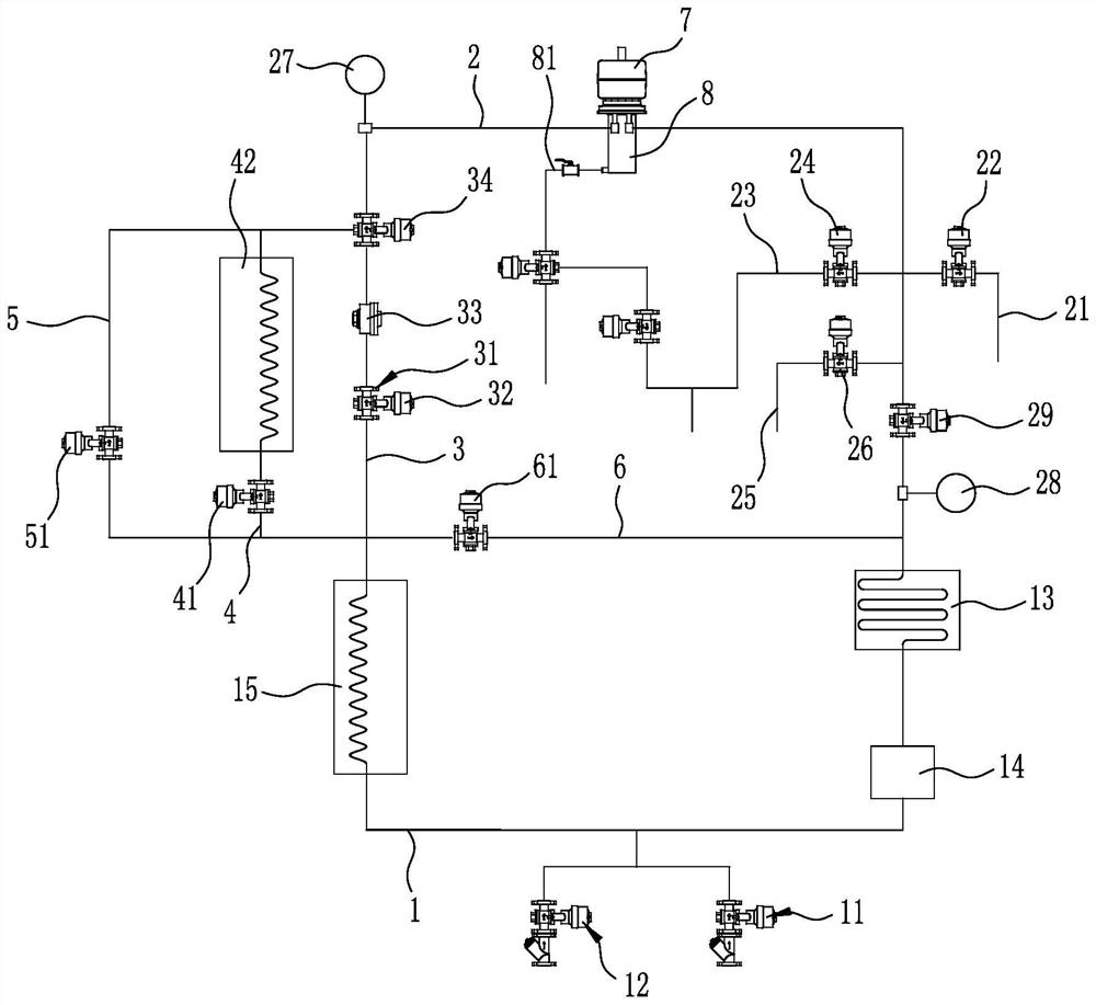
[0028] like figure 1 As shown, the self-circulating nitrogen heating system of the vulcanizer includes an air supply pipeline 1, and the air supply pipeline 1 is connected with a low-pressure air intake device 11 and a high-pressure air intake device 12. The low-pressure air inlet device 11 is used to supply low-pressure nitrogen gas to the air supply line 1 , and the high-pressure air inlet ...


PUM


Abstract

The invention discloses a vulcanizing machine self-circulation nitrogen heating system and a heating method. The heating system comprises an air supply pipeline, and the air supply pipeline is connected with a low-pressure air inlet device and a high-pressure air inlet device. A radiator, a gas circulating pump and a low-temperature gas heater are sequentially arranged on the gas supply pipeline; a main circulation pipeline and a preheating circulation pipeline which are arranged in parallel are connected between the tail end and the head end of the air supply pipeline, a preheating circulation valve is arranged on the preheating circulation pipeline, and a shaping ventilation pipeline, a high-temperature ventilation pipeline and a low-temperature ventilation pipeline which are arranged in parallel are connected between the head end of the main circulation pipeline and the tail end of the air supply pipeline. A shaping stop valve group is arranged on the shaping ventilation pipeline, a high-temperature stop valve and a high-temperature gas heater are arranged on the high-temperature ventilation pipeline, a low-temperature stop valve is arranged on the low-temperature ventilation pipeline, and a total circulation stop valve is arranged at the tail end of the total circulation pipeline. According to the invention, better temperature and pressure control can be realized, energy waste is reduced, and the vulcanization quality is improved.

Description

technical field [0001] The invention relates to the technical field of bladder vulcanizers, in particular to a self-circulating nitrogen heating system and a heating method for a vulcanizer. Background technique [0002] The bladder vulcanizer uses the molding method to manufacture tires. During the vulcanization process, the bladder is heated by a heating medium, and the outer mold is heated by electric heating. In the traditional capsule vulcanizer, the inside of the capsule is heated by high-temperature steam heated by a boiler. During the entire bladder vulcanization process, different pressures and temperatures of the heating medium need to be adjusted at different times, and the pressure of high-temperature steam, especially the temperature control, is difficult to adapt to this adjustment, so only the initial preheating and heating of the bladder is carried out with steam. , and during normal bladder vulcanization operations, electric heating nitrogen is used for sel...

Claims


Application Information

Patent Timeline
Patent Type & Authority Applications(China)
IPC IPC(8): B29D30/06B29C35/04B29L30/00
Inventor 王阳王京东张友京徐立波
Owner 山东阳光盛世机械装备有限公司
Why Eureka
Try Eureka