Ultrasonic surgical equipment control system

A technology for surgical operation and equipment control, which is applied in the fields of surgery, automatic power control, medical science, etc., and can solve the problems of inability to adapt to fast equivalent load environment, heating and changes of piezoelectric transducers, etc.

Active Publication Date: 2022-07-01
ANJIN MEDICAL TECH BEIJING
View PDF9 Cites 0 Cited by
  • Summary
  • Abstract
  • Description
  • Claims
  • Application Information

AI Technical Summary

Problems solved by technology

[0004]1. The tip of the scalpel is small, and it is in use with various media (air, water, tissue solution), biological tissues (soft tissue, calcified tissue, bone tissue, etc.) ) phase contact, the contact area changes greatly, so the equivalent load impedance of the piezoelectric transducer in the circuit will change greatly. The power supply cannot adapt to such a large variation range of the equivalent load impedance, and cannot drive the piezoelectric transducer to work normally under some conditions
[0005]2. The piezoelectric transducer will heat up after a certain period of time, which will cause the shift of the series resonance frequency of the transducer
At present, the ultrasonic surgical equipment that can perform frequency tracking has a slow response speed, and cannot adapt to the fast and constantly changing equivalent load environment, and output stable energy and effects in different load environments.

Method used


Image

  • Ultrasonic surgical equipment control system
  • Ultrasonic surgical equipment control system
  • Ultrasonic surgical equipment control system

Examples


Embodiment Construction

[0037] In order to make the purposes, technical solutions and advantages of the embodiments of the present invention clearer, the embodiments of the present invention will be further described in detail below with reference to the accompanying drawings. Here, the exemplary embodiments of the present invention and their descriptions are used to explain the present invention, but not to limit the present invention.

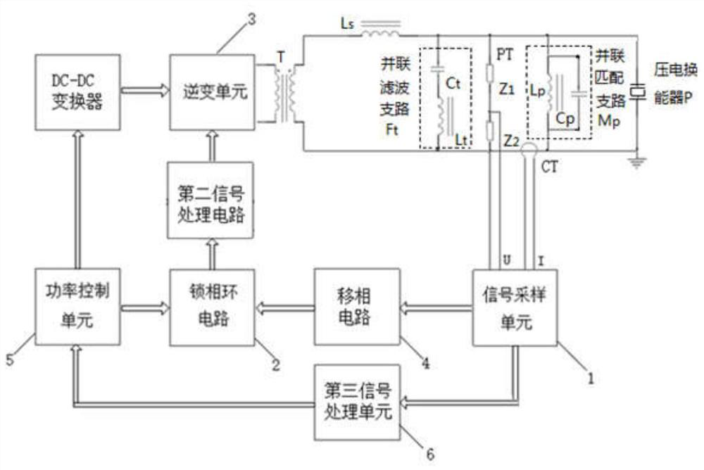
[0038] Embodiments of the present invention provide an ultrasonic surgical equipment control system, such as figure 1 As shown, the system includes: a piezoelectric transducer P, a first inductor L S , parallel matching branch M P , voltage transformer PT, parallel filter branch F t , a current transformer CT, and a signal sampling unit 1 , a phase-locked loop circuit 2 and an inverter unit 3 that are electrically connected in sequence. Among them, the piezoelectric transducer P and the first inductance L S connected in series, and the two form a closed loop. P...


PUM


Abstract

The invention discloses an ultrasonic surgical operation equipment control system. The system comprises a piezoelectric transducer P, a first inductor LS, a parallel matching branch MP, a parallel filtering branch Ft, a voltage transformer PT, a current transformer CT, and a signal sampling unit, a phase-locked loop circuit and an inversion unit which are electrically connected in sequence. The parallel matching branch MP is matched with the piezoelectric transducer P; a filter circuit composed of the first inductor LS and the parallel filter branch Ft performs frequency selection and equivalent impedance allocation; the hardware phase-locked loop circuit generates a frequency signal and performs fast frequency tracking. The voltage transformer PT and the current transformer CT feed back voltage and current on the piezoelectric transducer P to the phase-locked loop circuit, the phase-locked loop circuit automatically adjusts the output frequency to the same phase of voltage and current signals, and the piezoelectric transducer P is in the optimal resonance working state. The method can adapt to a large change range of equivalent load impedance of the piezoelectric transducer P, the frequency tracking speed is high, and the output power stability is good.

Description

technical field [0001] The invention relates to the field of medical equipment, in particular to an ultrasonic surgical equipment control system. Background technique [0002] Ultrasonic surgical equipment that uses piezoelectric transducers as electro-acoustic conversion elements and uses ultrasonic vibration energy for surgical operations has been widely used in hepatobiliary surgery, neurosurgery, orthopedics, ophthalmology and other surgical fields to realize the cutting of human tissue. Open, crush, emulsify, coagulate and stop bleeding. Due to the unique tissue selectivity of ultrasonic energy, ultrasonic surgical equipment has a good application prospect in the above-mentioned surgical field. [0003] At present, medical ultrasonic surgical equipment using piezoelectric transducers has at least the following characteristics and problems: [0004] 1. The tip of the scalpel head is small and in use, it is in contact with various media (air, water, tissue solution), bi...

Claims


Application Information

Patent Timeline
IPC IPC(8): A61B17/32H03L7/16
CPCA61B17/320068H03L7/16A61B2017/00017A61B2017/00137Y02B70/10
Inventor 赵伟郭志刚李帅
Owner ANJIN MEDICAL TECH BEIJING
Why Eureka
Try Eureka