Permanent magnet rotary motor and compressor using the same

A technology of rotating electrical machines and permanent magnets, applied in the field of permanent magnet rotating electrical machines, can solve the problems of ineffective mid-frequency band noise and incapable of sufficiently reducing the high-order harmonic components of the magnetic flux in the machine, so as to reduce the pulsating torque and improve the The effect of hearing sense of frequency band and reducing high-order harmonic components

Inactive Publication Date: 2012-10-24
HITACHI LTD
View PDF1 Cites 0 Cited by
  • Summary
  • Abstract
  • Description
  • Claims
  • Application Information

AI Technical Summary

Problems solved by technology

[0007] However, in the method of Patent Document 1 of the above-mentioned prior art, although the noise generated in the lower frequency band and the higher frequency band can be reduced, it cannot be said that it is effective for the problematic middle frequency band noise.
[0008] The reason is that, in the case of Patent Document 1, although the high-order harmonic components are reduced as the magnetic flux generated by the rotor, in practice, the high level of the internal magnetic flux combined with the magnetic flux generated by the stator cannot be sufficiently reduced. Subharmonic components

Method used


Image

  • Permanent magnet rotary motor and compressor using the same
  • Permanent magnet rotary motor and compressor using the same
  • Permanent magnet rotary motor and compressor using the same

Examples


Embodiment 1

[0076] Figure 7 It is a cross-sectional view showing the shape of the stator core of Embodiment 1 of the permanent magnet type rotating electrical machine of the present invention. Figure 8 It is a figure which shows the shape of the stator core of Embodiment 1 of the permanent magnet type electric rotating machine of this invention. Figure 12 The cross-sectional structure of the compressor of the present invention is shown, and Table 1 shows the results of hearing tests on compressors with various rotating electrical machine structures.

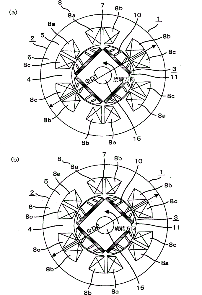
[0077] figure 1 It is a sectional view showing Embodiment 1 of the permanent magnet type rotating electric machine of the present invention.

[0078] exist figure 1 Among them, a permanent magnet rotating electrical machine 1 includes a stator 2 and a rotor 3 . The stator 2 includes a stator core 6 and a concentratedly wound armature winding 8 (composed of U-phase winding 8a, V-phase winding 8b, and W-phase winding 8c of the three-pha...

Embodiment 2

[0111] Next, other embodiments of the present invention will be described.

[0112] Figure 9 Showing the stator core shape of Embodiment 2 of the permanent magnet type rotating electric machine of the present invention, with respect to Figure 7 The same components are given the same symbols. In the figure, with Figure 7 The difference is that two protrusions 80 consisting of 80a and 80b are formed outside the outer circumference of the stator section B, and the outer peripheral surface of the protrusions 80 is the same diameter (ΦD1) as the outermost circumference of the stator section A. Thus, when the stator 2 is formed from the stator section A and the stator section B, since the diameters of the outermost peripheries are the same, stacking can be performed without misalignment using the stator core outer periphery as a reference position. Here, although two protrusions 80 are provided on the outer periphery of each groove 7, one may be provided, and an arbitrary numb...

Embodiment 3

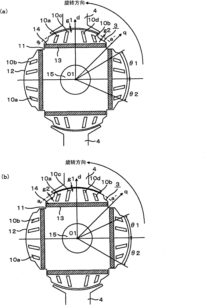
[0114] Figure 10 It is a figure showing the shape of the rotor core of Embodiment 3 of the permanent magnet type rotating electrical machine of the present invention. Figure 4 The same components are given the same symbols. In the figure, with Figure 4 The different part is that the lamination thickness ratio of the rotor section A is configured so that 50%A figure 2 same effect.


PUM


Abstract

The invention provides a low-vibration, low-noise permanent magnet rotary motor and compressor using the same. In order to provide the low-vibration, low-noise permanent magnet rotary motor and compressor using the same, the invention considers the armature reaction to completely reduce the higher harmonic component of the magnetic flux in the motor and forms a stator core shape to make the radial electromagnetic vibration-helping force in the motor difficult to be transferred to the frame of the compressor. The higher harmonic component of the magnetic flux in the motor is reduced, the pulsetorque is reduced, and the vibration from the rotor cross-section of the relatively middle zone with increasing radial electromagnetic vibration-helping force to the frame of the compressor is suppressed, therefore a permanent magnet rotary motor capable of greatly improving the hearing feeling of the middle zone and a compressor using the same are provided.

Description

technical field [0001] The present invention relates to a permanent magnet type rotating electrical machine including permanent magnets for excitation in a rotor. Background technique [0002] Conventionally, in a permanent magnet type rotating electrical machine, concentrated winding is used for a stator winding, and a rare-earth neodymium permanent magnet is used as an excitation to achieve high efficiency. In addition, as the magnetic flux density of magnet materials increases, vibration and noise components also become more pronounced, and various countermeasures for these problems are required. [0003] For example, in the permanent magnet type rotating electrical machine described in Patent Document 1, it is proposed to provide a plurality of slits extending from the outer peripheral side of the permanent magnet embedded in the rotor to the outer peripheral side of the rotor. A plurality of gap surfaces are provided on the outer periphery of the rotor, and the gap sur...

Claims


Application Information

Patent Timeline
Patent Type & Authority Patents(China)
IPC IPC(8): H02K21/14H02K1/27F04B35/04
Inventor 高畑良一菊地聪涌井真一野间启二妹尾正治
Owner HITACHI LTD
Why Eureka
Try Eureka