Roadbed supporting structure

A technology for supporting structures and roadbeds, applied in infrastructure engineering, roads, roads, etc., can solve problems such as longer engineering cycles, and achieve the effects of improving bearing effect, increasing strength, and reducing costs

Pending Publication Date: 2022-06-28
中铁二院成都勘察设计研究院有限责任公司
View PDF17 Cites 0 Cited by
  • Summary
  • Abstract
  • Description
  • Claims
  • Application Information

AI Technical Summary

Problems solved by technology

[0002] The subgrade is the foundation of the track or road surface, and it is a geotechnical structure formed by excavation or filling; the main function of the subgrade is to provide necessary conditions for the laying of the track or road surface and the operation of trains or driving, generally for soft soil areas with a depth of more than 3 meters Composite foundation is often used for reinforcement, and a layer of geogrid gravel cushion is laid on the top of the composite foundation; usually the treatment of composite foundation is usually reinforced with rotary grouting piles. In order to meet the bearing capacity and post-construction settlement requirements of the railway, within the scope of the railway Composite foundation treatment is required, and jet grouting piles are underground projects, which will lead to the use of jet grouting piles for reinforcement within the railway range, making the project period longer

Method used


Image

  • Roadbed supporting structure
  • Roadbed supporting structure
  • Roadbed supporting structure

Examples


Embodiment 1

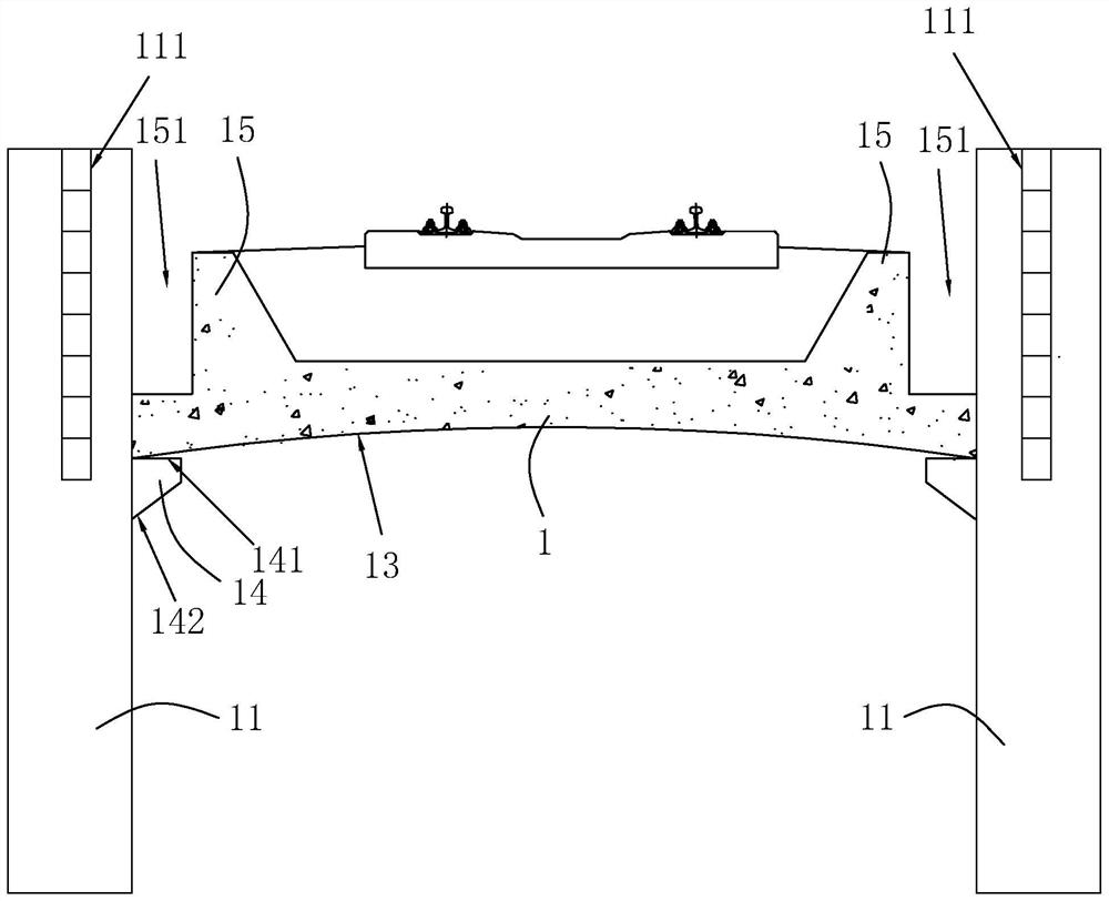
[0036] The embodiments of the present application disclose a roadbed support structure. refer to figure 1 , a roadbed support structure, including a base body 1, the base body 1 is made of concrete, and the roadbed support structure also includes a bearing member and a support member, the bearing member is used to carry the load on both sides of the base body 1, and the support member is used to The bottom of the base body 1 is supported.

[0037] like figure 1 As shown, the bearing member includes a plurality of bearing piles 11 arranged on both sides of the base body 1 and along the length direction of the base body 1, and the base body 1 is arranged on the plurality of bearing piles 11 on both sides; Retaining wall 111; in this embodiment, the bearing pile 11 is set as a pile foundation, and the pile foundation is a deep foundation composed of piles and a pile cap (referred to as a cap) connecting the top of the pile or a single foundation connected by a column and a pile...

Embodiment 2

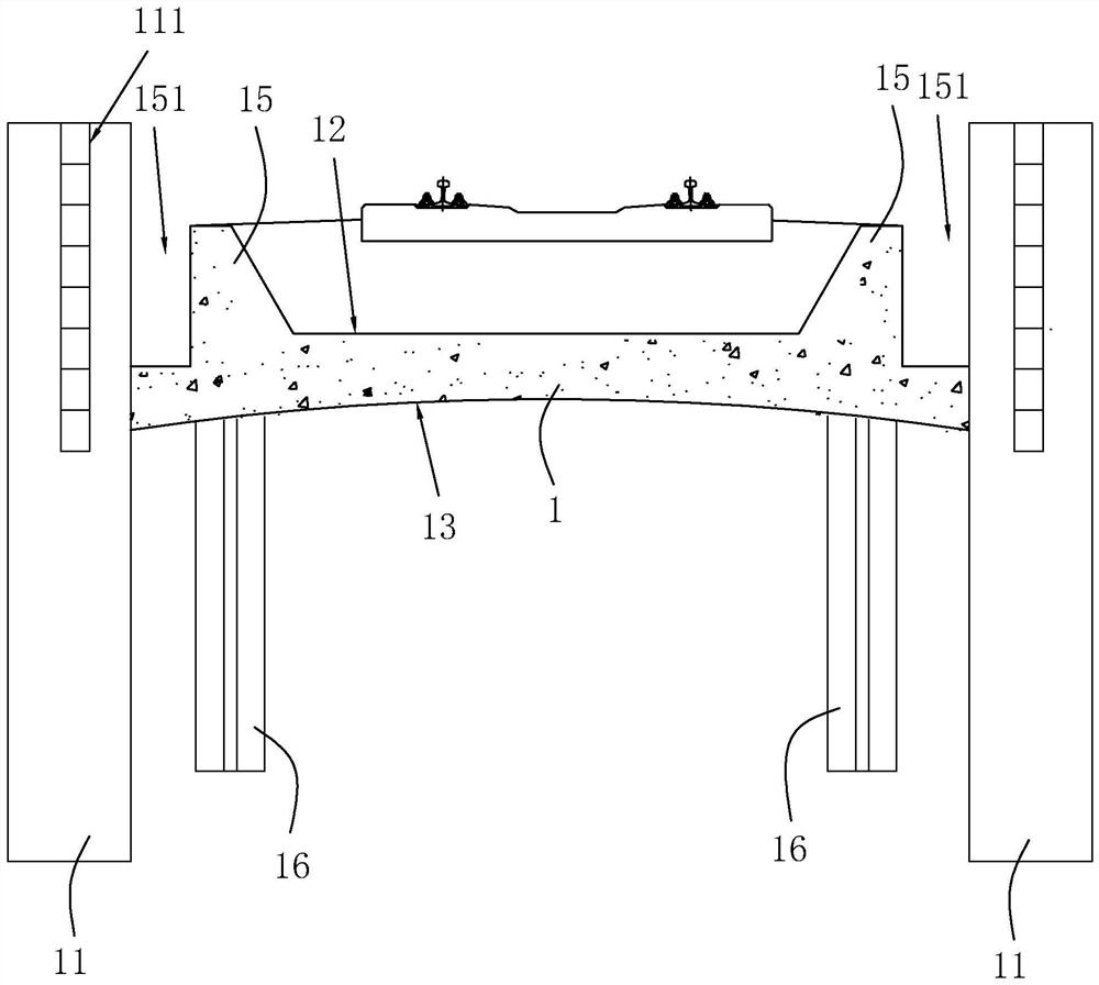
[0043] The difference between this embodiment and the first embodiment is that: figure 2 As shown, the support member includes support piles 16 , which are arranged in the vertical direction, and a plurality of support piles 16 are arranged below the base body 1 and on both sides of the base body 1 , and the plurality of support piles 16 are arranged along the length direction of the base body 1 . There are multiple groups. In this embodiment, four support piles 16 are provided below the base body 1 and located on both sides of the base body 1. The base body 1 is arranged on multiple groups of support piles 16, and the support piles 16 are set as rotary spray piles. The spray pile is to use the drilling rig to place the rotary jet grouting pipe and the nozzle at the design elevation of the pile bottom. After the pre-prepared slurry is passed through the high-pressure generating device, the liquid flow obtains huge energy, and then it is sprayed out from the nozzle at the side ...

Embodiment 3

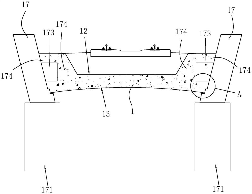
[0046] The difference between this embodiment and the first embodiment is that: image 3 As shown, the bearing member includes a bearing wall 17, both sides of the base body 1 are provided with bearing walls 17 along the length direction of the base body 1, and the distance between the bearing walls 17 on both sides is gradually along the direction from the bearing surface 12 to the force transmission surface 13. Reduced, the base body 1 is arranged between the bearing walls 17 on both sides; in this embodiment, the bearing walls 17 are arranged as gravity retaining walls, and the gravity retaining walls 111 are in the prior art, and the specific structure will not be carried out. In other embodiments, the distance between the opposite sides of the bearing walls 17 on both sides can also be gradually reduced, and the opposite sides of the bearing walls 17 on both sides are arranged vertically along the vertical direction.

[0047] like image 3 As shown, in order to further i...


PUM


Abstract

The invention relates to a roadbed supporting structure which comprises a base body, the roadbed supporting structure further comprises a bearing part and a supporting part, the bearing part is used for bearing the two sides of the base body, the supporting part is used for supporting the bottom of the base body, the top wall of the base body is arranged to be a bearing face, the bottom wall of the base body is arranged to be a stress transmission face, and the bearing face is arranged on the bearing face. The cross section of the stress transmission surface is arranged in an arc shape, a notch of the arc-shaped stress transmission surface is arranged in a direction deviating from the bearing surface, and the arc-shaped stress transmission surface is used for transmitting a load on the bearing surface to a bearing part; the supporting structure has the advantages that the construction cost of the jet grouting pile reinforcing area is reduced, and the supporting structure is balanced in stress and sufficient in stress.

Description

technical field [0001] The present application relates to the field of roadbed treatment, in particular to a roadbed support structure. Background technique [0002] The subgrade is the foundation of the track or pavement, and is a geotechnical structure formed by excavation or filling; the main function of the subgrade is to provide the necessary conditions for the laying of the track or pavement and the operation of trains or traffic, generally for soft soil areas with a depth of more than 3 meters. , Composite foundation is often used for reinforcement, and a layer of geogrid crushed stone cushion is laid on the top of the composite foundation; usually, the treatment of composite foundation is usually reinforced by rotary jet piles. The composite foundation needs to be treated, and the rotary jet pile is an underground project, which will lead to the use of rotary jet pile reinforcement in the railway range, which will make the project cycle longer. SUMMARY OF THE INVEN...

Claims


Application Information

Patent Timeline
Patent Type & Authority Applications(China)
IPC IPC(8): E01C3/00E01C3/04E02D5/46E01C3/06
CPCE01B2/006E02D5/46
Inventor 李永奎杨贵勇徐宇徐海涛龙红宇唐科行马鹏陈子龙张忠黄培敏汤骄李果汪琳张笔畅贾昊
Owner 中铁二院成都勘察设计研究院有限责任公司
Why Eureka
Try Eureka