
Screw conveyer and shield tunneling machine

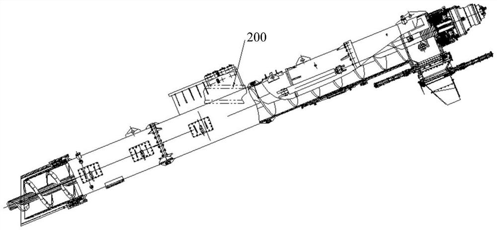
A technology of screw conveyor and shield machine, applied in the field of shield machine and screw conveyor, can solve the problems of difficult processing and high cost of joint ball bearings, and achieve the advantages of reducing processing difficulty and production cost, simple structure and reducing impact. Effect

Pending Publication Date: 2022-06-24
CHINA RAILWAY CONSTR HEAVY IND
View PDF0 Cites 0 Cited by
  • Summary
  • Abstract
  • Description
  • Claims
  • Application Information

AI Technical Summary

Problems solved by technology

[0004] At present, the hinge device commonly used in screw conveyors is joint ball bearings. However, joint ball bearings have the problems of difficult processing and high cost.

Method used


Image

  • Screw conveyer and shield tunneling machine
  • Screw conveyer and shield tunneling machine
  • Screw conveyer and shield tunneling machine

Examples


Embodiment Construction

[0038] The technical solutions in the embodiments of the present invention will be clearly and completely described below with reference to the accompanying drawings in the embodiments of the present invention. Obviously, the described embodiments are only a part of the embodiments of the present invention, but not all of the embodiments. Based on the embodiments of the present invention, all other embodiments obtained by those of ordinary skill in the art without creative efforts shall fall within the protection scope of the present invention.

[0039] The core of the present invention is to provide a screw conveyor, which can meet the requirements of the shield machine for turning with a small curve radius, and has low processing difficulty and low cost. Another core of the present invention is to provide a shield machine including the above-mentioned screw conveyor. The screw conveyor can meet the requirements of the shield machine for turning with a small curve radius, and ...


PUM


Abstract

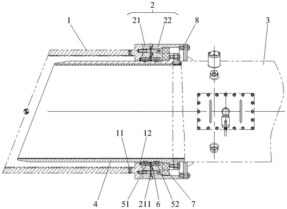
The invention discloses a screw conveyer and a shield tunneling machine. The screw conveyer comprises a shield body sleeve, a screw rod and a screw rod, wherein the shield body sleeve is connected with a front shield body of the shield tunneling machine; the outer cylinder is connected with the shield body sleeve; a screw conveyor cylinder; the inner barrel is connected with the spiral conveyor barrel and arranged in the outer barrel and the shield body sleeve, and gaps are formed between the inner barrel and the outer barrel and between the inner barrel and the shield body sleeve; and the elastic sealing piece is arranged between the inner cylinder and the outer cylinder. When the shield tunneling machine turns, the inner barrel extrudes the elastic sealing piece, so that the inner barrel drives the barrel body of the spiral conveyor to float up, down, left and right within a certain range, and the situation that when the shield tunneling machine turns with a small curve radius, the swing amount of the tail of the spiral conveyor is too large, and the shield tunneling machine turns with a small curve radius is avoided. The spiral conveyor can well meet the requirement for small-curve-radius turning of the shield tunneling machine, and the use reliability of the shield tunneling machine is improved. Compared with the prior art that a joint ball bearing is adopted for achieving connection of the spiral conveyor and the shield tunneling machine, the structure is simple, and the machining difficulty and the production cost are reduced.

Description

technical field [0001] The invention relates to the technical field of tunnel construction equipment, and more particularly, to a screw conveyor. In addition, the present invention also relates to a shield machine comprising the above-mentioned screw conveyor. Background technique [0002] In tunnel projects such as urban subways and underground pipelines, shield tunneling machines are usually used for shield construction. The shield machine includes a screw conveyor, and the screw conveyor passes through the shield body of the shield machine and is connected to the back supporting system of the shield machine, which is used to convey the ballast soil excavated by the cutter head. [0003] With the increase in the construction demand of small curve tunnels, higher requirements are put forward for the steering capacity of the shield machine. When turning with a small curve radius, the front and rear sections of the shield machine will move relative to each other. . When the...

Claims


Application Information

Patent Timeline
Patent Type & Authority Applications(China)
IPC IPC(8): E21D9/12E21D9/06
CPCE21D9/124E21D9/06
Inventor 彭正阳万佩廖倩陈朗
Owner CHINA RAILWAY CONSTR HEAVY IND
Learn More