Box beam welding device and box beam welding manufacturing method

A technology of welding device and manufacturing method, which is applied in the direction of welding equipment, manufacturing tools, welding equipment, etc., can solve the problems of difficult automatic welding and large floor area, and achieve improved welding manufacturing efficiency, high welding efficiency, and reduced The effect of occupying the area of ​​the site

Pending Publication Date: 2022-06-21
SHENZHEN RILAND IND
View PDF0 Cites 0 Cited by
  • Summary
  • Abstract
  • Description
  • Claims
  • Application Information

AI Technical Summary

Problems solved by technology

In addition, the back penetration in the conventional welding method is difficult to control, and usually requires manual welding to make the bottom, and it is difficult to achieve fully automatic welding
In order to increase the welding capacity, it is usually necessary to arrange multiple identical stations for parallel production, so the floor space is large

Method used


Image

  • Box beam welding device and box beam welding manufacturing method
  • Box beam welding device and box beam welding manufacturing method
  • Box beam welding device and box beam welding manufacturing method

Examples


Embodiment Construction

[0047] The technical solutions in the embodiments of the present invention will be clearly and completely described below with reference to the accompanying drawings in the embodiments of the present invention. Obviously, the described embodiments are only a part of the embodiments of the present invention, but not all of the embodiments. Based on the embodiments of the present invention, all other embodiments obtained by those of ordinary skill in the art without creative efforts shall fall within the protection scope of the present invention.

[0048] It should be noted that if there are directional indications (such as up, down, left, right, front, back, etc.) involved in the embodiments of the present invention, the directional indications are only used to explain a certain posture (as shown in the accompanying drawings). If the specific posture changes, the directional indication also changes accordingly.

[0049] In addition, if there are descriptions involving "first", ...


PUM


Abstract

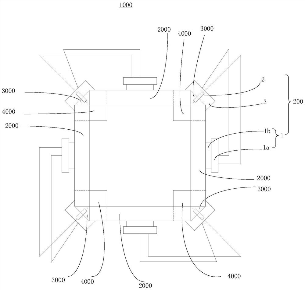
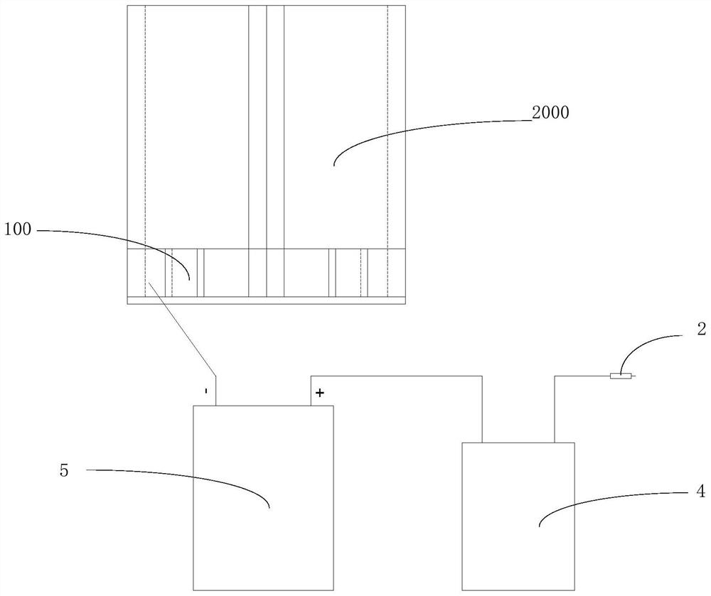
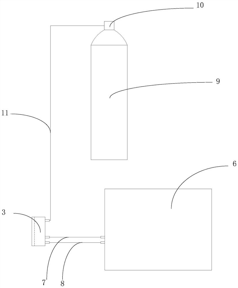
The invention discloses a box beam welding device and a box beam welding manufacturing method.The box beam welding device is used for connecting at least three welding plates through welding to form a box beam and comprises a fixing base and a plurality of welding assemblies, and the fixing base is used for fixing the bottoms of the at least three welding plates; vertically placing the at least three welding plates so as to enclose a box beam with at least three welding seams; the multiple welding assemblies are used for being arranged in one-to-one correspondence with the welding seams, each welding assembly comprises a walking mechanism, a welding gun and a water cooling sliding block, the welding gun and the water cooling sliding block are installed on the walking mechanism, the walking mechanisms are detachably installed on the welding plate, and the walking mechanisms are provided with moving paths along the outer side face of the welding plate and used for driving the welding guns and the water cooling sliding blocks to move. And a welding zone is defined by the welding seam forming face of the water-cooling sliding block and the side faces of the two adjacent welding plates. According to the scheme, the structure is simple, the adaptability is good, the welding manufacturing efficiency of the box beam is improved, and the occupied field area is reduced.

Description

technical field [0001] The invention relates to the technical field of welding, in particular to a box beam welding device and a box beam welding manufacturing method. Background technique [0002] Box beam is a common form of metal structure, and its section shape is generally rectangular, which is the same as the usual box section, so it is called box beam, which is widely used in various construction machinery and metal structures for construction. [0003] The box beam is generally welded by four plates. The welding workload is large during the manufacturing process, and the welding deformation is large and requires post-weld correction. The traditional welding method of the box beam is horizontal position welding, and the four welds need to be rotated by the positioner and welded in sequence. In order to reduce the amount of welding deformation, multi-layer multi-pass welding of thick plates is usually not completed at one time, but one weld should be welded in stages....

Claims


Application Information

Patent Timeline
Patent Type & Authority Applications(China)
IPC IPC(8): B23K31/02B23K37/00B23K37/02
CPCB23K31/02B23K37/0217B23K37/003
Inventor 李阳朝吴彬彬邱光耿正王魏
Owner SHENZHEN RILAND IND
Why Eureka
Try Eureka