A new energy vehicle battery management cooling device
A new energy vehicle and battery management technology, which is applied in the field of heat dissipation devices for battery management of new energy vehicles, can solve the problems of inability to guarantee the battery, inability to guarantee the heat dissipation effect, inconvenient heat distribution due to the centralized heat generation, etc., so as to avoid centralized heat generation and prolong the The effect of the overall service life
- Summary
- Abstract
- Description
- Claims
- Application Information
AI Technical Summary
Problems solved by technology
Method used
Image
Examples
Embodiment 1
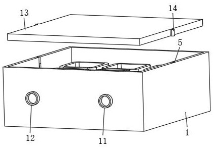
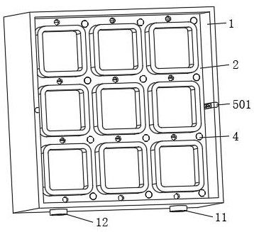
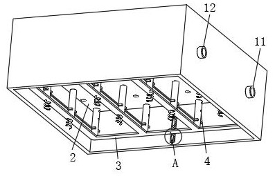
[0034] see Figure 1 to Figure 6 , an embodiment of the present invention provides a heat dissipation device for battery management of a new energy vehicle: comprising a box body 1, a base 2 is fixedly installed inside the box body 1, and the upper surface of the base 2 is fixedly installed in a rectangular array and used for placement There are several fixing bases for the battery, in this embodiment, there are nine fixing bases; the front surface of the box 1 is fixedly installed with an air inlet 11 and an air outlet 12, and the air inlet 11 is located on the right side in this embodiment.
[0035] The inside of the box body 1 is provided with a guide assembly 3 that is connected to the air inlet 11. The guide assembly 3 includes a guide plate 301 and a circular tube 302 that are connected to each other. The air outlet assembly 4 extending out of the base 2 includes a first connecting pipe 401 and a plurality of second connecting pipes 402 that are both connected to the gui...
Embodiment 2
[0041] see Figure 1 to Figure 8 , on the basis of the first embodiment, a spring is fixedly installed between the bottom of the guide plate 301 and the bottom wall of the box 1, and the spring is set so that the guide plate 301 can move up and down relative to the base 2, and is used for the guide plate 301 Reset after moving; the end of the round pipe 302 away from the baffle 301 is connected to the air inlet 11 through a hose, and the setting of the hose can provide feasibility for the movement of the baffle 301 .
[0042] The surfaces of the first connecting pipe 401 and the second connecting pipe 402 are provided with air holes through them, and the air holes are opened above the base 2; the interior of the first connecting pipe 401 and below the air holes are rotated and installed with a number of fan-shaped torsion springs. The plate 403, in this embodiment, there are four fan-shaped plates 403 arranged in a circular array along the inner wall of the first connecting pi...
Embodiment 3
[0049] see Figure 1 to Figure 11 On the basis of the second embodiment, the first connecting pipe 401 and the second connecting pipe 402 both include two short pipes 9 arranged up and down, and the air holes are correspondingly arranged on the upper short pipe 9 and the second connecting pipe 401 of the first connecting pipe 401. On the upper short pipe 9 of the connecting pipe 402, and the upper short pipe 9 and the base 2 are in a sliding fit state; the fan-shaped plate 403 is arranged on the lower short pipe 9 of the first connecting pipe 401, and the partition plate 404 is arranged on the second connecting pipe. 402 on the lower short pipe 9, and the lower short pipe 9 is fixedly connected with the baffle 301. The bottom of the upper short tube 9 is fixedly connected with a hollow telescopic tube 7, the movable end of the hollow telescopic tube 7 is rotatably connected with the lower short tube 9, and the hollow telescopic tube 7 is kept connected with the upper short tub...
PUM
 Abstract
Description
Claims
Application Information
 - R&D
- Intellectual Property
- Life Sciences
- Materials
- Tech Scout
- Unparalleled Data Quality
- Higher Quality Content
- 60% Fewer Hallucinations
Browse by: Latest US Patents, China's latest patents, Technical Efficacy Thesaurus, Application Domain, Technology Topic, Popular Technical Reports.
© 2025 PatSnap. All rights reserved.Legal|Privacy policy|Modern Slavery Act Transparency Statement|Sitemap|About US| Contact US: help@patsnap.com


