Method for producing battery cell

A battery cell, single cell technology, applied in the direction of manufacturing tools, secondary batteries, battery assembly machines, etc., to achieve the effects of increasing power, reducing ohmic heat loss, and increasing current

Pending Publication Date: 2022-06-10
VOLKSWAGEN AG
View PDF1 Cites 0 Cited by
  • Summary
  • Abstract
  • Description
  • Claims
  • Application Information

AI Technical Summary

Problems solved by technology

This means that relatively high (ohmic) power losses occur in the region of the laser weld seam

Method used


Image

  • Method for producing battery cell
  • Method for producing battery cell
  • Method for producing battery cell

Examples


Embodiment Construction

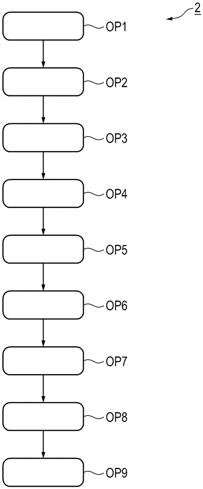
[0042] As an alternative to the method step OP1 described above, it is conceivable, for example, to clean the current conductors 8 , 10 by means of a plasma.

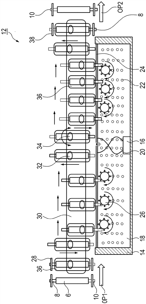
[0043] Once the surface has been cleaned, it is preheated in method step OP2 by induction or resistance heating under an inert nitrogen atmosphere ( Figure 4 ). For example, in the case of resistive heating, two energizable plungers are pressed onto the current conductors 8 , 10 . The plunger here is in particular made of graphite, titanium or tungsten.

[0044] In the case of the copper anode of the current conductor 10 , it is preheated, for example, up to 600° C. In the case of the aluminum cathode of the current conductor 8 , preheating is carried out up to 300° C., for example. For this purpose, the device has a heating chamber as housing 40 . The heating chamber 40 has a gas 42 inside it.

[0045] The inert gas 42 is designed as nitrogen, for example, and is introduced into the heating chamber 40 at an exces...


PUM

PropertyMeasurementUnit
yield stressaaaaaaaaaa

Abstract

The invention relates to a method (2) for producing a battery cell (4) having an electrode stack (6) with a plurality of first and second current conductors (8, 10) arranged one above the other, the first current conductor (8) being integrally bonded to a common cathode (62) without melting and the second current conductor (10) being integrally bonded to the common cathode (62). The first current conductor (8) and the second current conductor (10) are joined in a non-fusible cohesive manner to form a common anode (64), and wherein the first and the second current conductor (8, 10) are joined by thermocompression bonding to form a cathode (62) and an anode (64).

Description

technical field [0001] The invention relates to a method for producing a battery cell, for example for producing pouch cells, which has an electrode stack with a plurality of first and second current conductors. The invention also relates to a device for carrying out the method and to a battery cell. Background technique [0002] An electrically or electrically propelled or drivable motor vehicle, such as an electric vehicle or a hybrid vehicle, generally comprises an electric motor with which one or two axles can be driven. To supply electrical energy, the electric motor is usually connected to a (high-voltage) battery inside the vehicle as an electrical energy store. [0003] Electrochemical cells are here and hereinafter in particular referred to as so-called secondary batteries (secondary batteries) of motor vehicles. In the case of such (secondary) vehicle batteries, the used chemical energy can be recovered by an electrical (charging) process. Such vehicle batteries...

Claims


Application Information

Patent Timeline
Patent Type & Authority Applications(China)
IPC IPC(8): H01M10/058H01M10/0585H01M50/536H01M50/538H01M10/0525B23K28/02B23K20/24B23K20/26B23K20/02
CPCH01M10/058H01M10/0585H01M50/536H01M50/538H01M10/0525B23K28/02B23K20/24B23K20/26B23K20/02H01M10/0404H01M10/0436Y02E60/10Y02P70/50
Inventor K·贾马达C·特尔考夫
Owner VOLKSWAGEN AG
Why Eureka
Try Eureka