Bridge cavity crack detector

A crack detector and cavity technology, which is applied in the direction of instruments, measuring devices, scientific instruments, etc., can solve the problems of difficult operation of devices, bridge destruction, and affecting the safe use of bridges, etc.

Active Publication Date: 2022-06-03
SHANDONG HUAJIAN ENG TESTING CO LTD
View PDF9 Cites 1 Cited by
  • Summary
  • Abstract
  • Description
  • Claims
  • Application Information

AI Technical Summary

Problems solved by technology

[0002] As the hub of traffic systems such as roads, highways, and railways, bridges need to be regularly inspected and tested to evaluate the damage status of bridges. As one of the most important bridge diseases, bridge cracks seriously affect the safety of bridges. More serious accidents of bridge destruction will occur. Therefore, it is very important to detect bridge cracks. At present, the main way of bridge detection is to use two groups of cantilever cranes to inspect a group of long The arm beam is hoisted, and the long arm beam is under the bridge. One detection method is that the operator stands on the long arm beam and moves to detect bridge cracks. The other way is to install the detection device through the screw slider mechanism. The detection is carried out on the long-arm crossbeam, but such an operation method will make it difficult for the device to perform obstacle avoidance operations during the movement process, resulting in poor flexibility of the device, and different types of long-arm crossbeams need to be used according to bridges of different widths. The limitations of the use of the device are greatly improved

Method used


Image

  • Bridge cavity crack detector
  • Bridge cavity crack detector
  • Bridge cavity crack detector

Examples


Embodiment 1

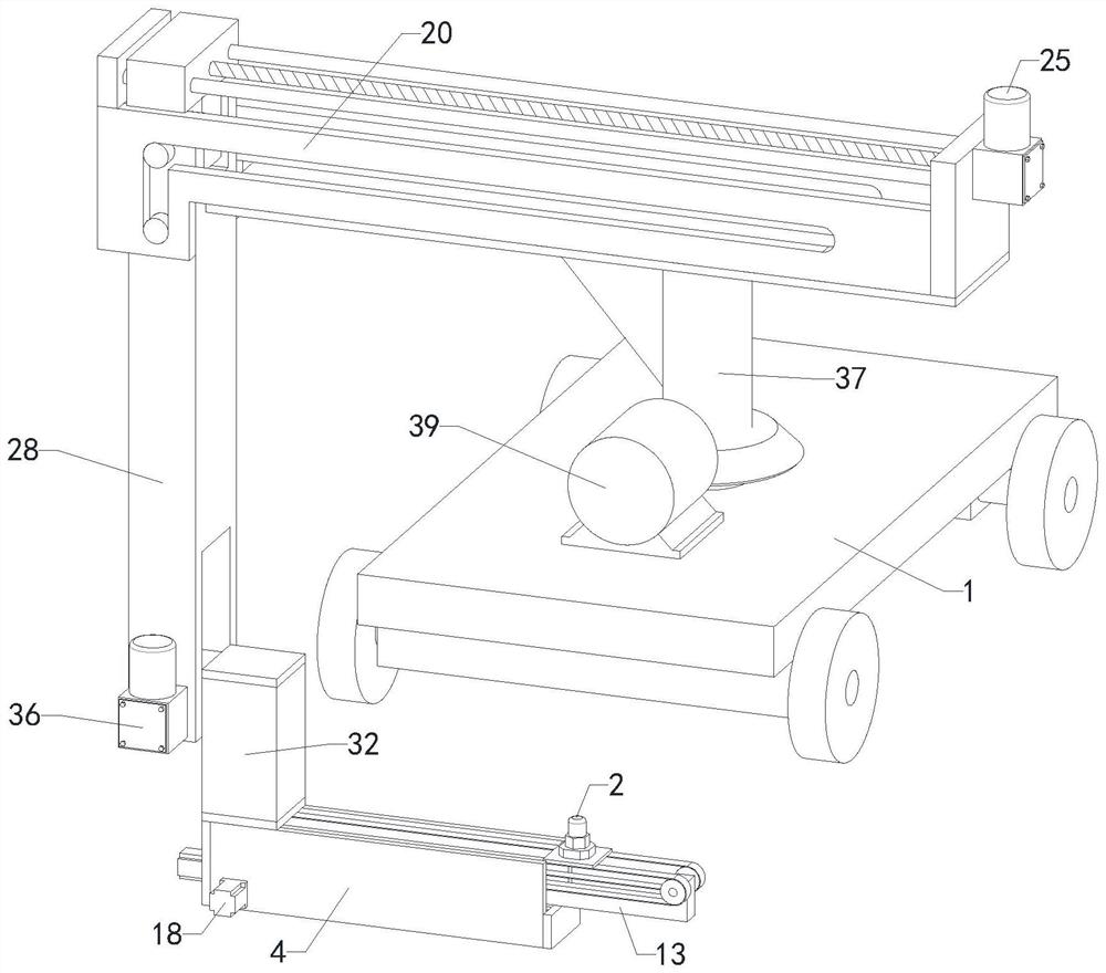
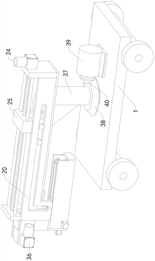
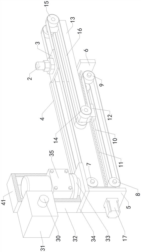
[0020] like Figure 1 to Figure 4 As shown, the support shaft 37 is rotatably installed on the vehicle frame 1, the support plate 19 is fixedly installed on the upper end of the support shaft 37, the first bevel gear 38 is fixedly installed on the support shaft 37, the motor 39 is fixedly installed on the vehicle frame 1, and the second bevel gear 38 is fixedly installed on the support shaft 37. The bevel gear 40 is fixedly connected with the output end of the motor 39, and the second bevel gear 40 and the connecting arm 28 are meshed with each other. On the right end face of the second set of fixing plates 20, the baffle D22 is fixedly installed on the left part of the upper end face of the two sets of second fixing plates 20, and the two sets of second sliding bars 23 are symmetrically and fixedly installed in the middle of the baffle D22 and the baffle C21. The second lead screw 24 is rotatably installed between the baffle D22 and the baffle C21, the first deceleration motor ...


PUM


Abstract

The invention relates to the technical field of bridge flaw detection, in particular to a bridge cavity crack detector, which can be folded, can automatically adjust the moving detection range of a flaw detection head according to bridges with different widths, and replaces the traditional operation mode by using a long-arm beam. The working flexibility of the device is improved; comprising a frame, a flaw detection head, a connecting plate, a telescopic moving assembly, a steering assembly and a folding assembly, the steering assembly is installed on the frame, the folding assembly is installed on the steering assembly, the flaw detection head is fixedly installed on the upper end face of the connecting plate, the connecting plate is installed on the telescopic moving assembly, and the telescopic moving assembly is installed on the folding assembly.

Description

technical field [0001] The invention relates to the technical field of bridge flaw detection, in particular to a bridge cavity crack detector. Background technique [0002] Bridges, as the hubs of roads, highways, railways and other transportation systems, need to be inspected and tested regularly to evaluate the damage status of bridges. Bridge cracks, as one of the most important bridge diseases, seriously affect the safety of bridges. If the bridge is used, the accident of bridge crash and death will occur more seriously. Therefore, it is very important to detect bridge cracks. At present, the main method for bridge detection is to use two sets of cantilever cranes on both sides of the bridge deck. The arm beam is hoisted, and the long-arm beam is under the bridge. One detection method is that the operator stands on the long-arm beam and moves to detect bridge cracks. Another method is to install the detection device through the lead screw slider mechanism. The detection...

Claims


Application Information

Patent Timeline
Patent Type & Authority Applications(China)
IPC IPC(8): G01B21/16G01N33/00
CPCG01B21/16G01N33/00Y02E30/30
Inventor 任士朴齐勤华李志双董凡荣王松张斌李丰王昭
Owner SHANDONG HUAJIAN ENG TESTING CO LTD
Why Eureka
Try Eureka