
Solar thermal power generator

A generator and thermal energy technology, applied in the field of solar power generation, can solve the problem of high power generation cost, achieve good heat storage effect, improve practical value, and lower unit cost

Pending Publication Date: 2022-06-03
陈见成
View PDF1 Cites 1 Cited by
  • Summary
  • Abstract
  • Description
  • Claims
  • Application Information

AI Technical Summary

Problems solved by technology

[0005] The purpose of the present invention is to provide a solar thermal power generator. Starting from the purpose of how to make the unit cost of electrical appliances much lower than the photovoltaic cost, in order to solve the problem of high power generation cost of the existing solar thermal power generator proposed by the above-mentioned background technology, the present invention sets out Glass screen and heat storage material. The glass screen is an infrared-transmitting glass screen, which can allow infrared rays to penetrate into the heat storage tank as much as possible while preventing the heat energy from being conducted out of the heat storage tank. The heat storage material uses azobenzene as a heat accumulator. material, so that the heat storage tank can keep generating electricity for a period of time when there is no light, and the thermoelectric conversion element can use the temperature difference to generate electricity, so that the unit cost of the generator is much lower than the photovoltaic cost, and the practical value is improved. By adding the first conveyor belt, The motor and the wiping rod, the motor drives the transmission rod and the first conveyor belt to rotate, the wiping rod and the wiping cotton slide down along the top of the glass screen to wipe off the dust on the outer wall of the glass screen, which is convenient for dust removal of the glass screen

Method used


Image

  • Solar thermal power generator
  • Solar thermal power generator
  • Solar thermal power generator

Examples


Embodiment Construction

[0024] The technical solutions in the embodiments of the present invention will be clearly and completely described below with reference to the accompanying drawings in the embodiments of the present invention. Obviously, the described implementation regulations are only a part of the embodiments of the present invention, rather than all the embodiments. Based on the embodiments of the present invention, all other embodiments obtained by those of ordinary skill in the art without creative efforts shall fall within the protection scope of the present invention.

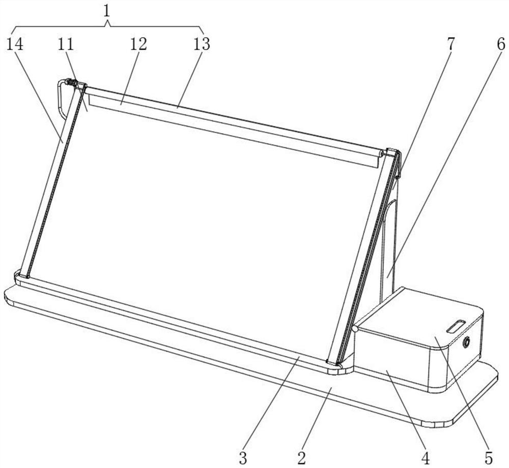
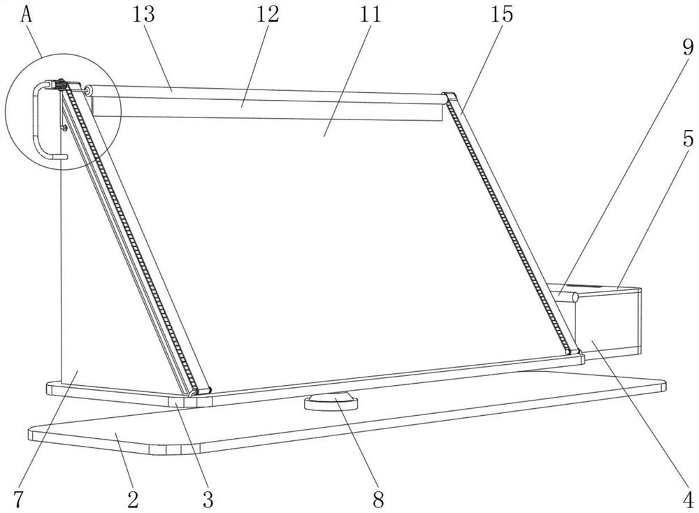
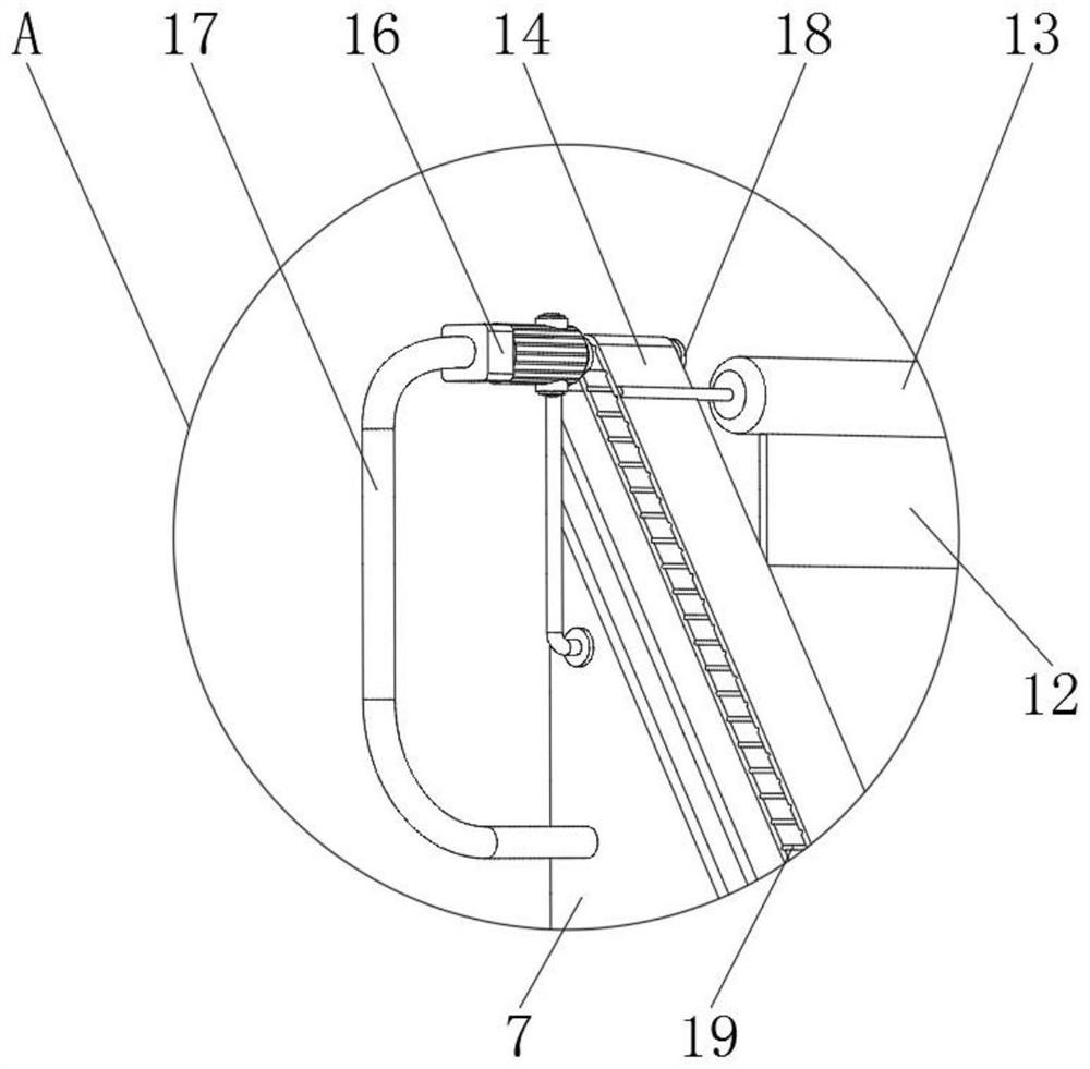
[0025] refer to Figure 1-5 Shown: solar thermal generator, including glass assembly 1, bottom plate 2, carrier plate 3, storage box 4, protective cover 5, movable seat 8, heat storage box 7, controller 22 and inverter 10, heat storage box 7 The top of the heat storage box 7 is fixedly installed with the bottom of the glass assembly 1, and the heat storage box 7 is provided with a heat storage material 24. The ammoniu...


PUM


Abstract

The invention discloses a solar thermal power generator which comprises a glass assembly, a bottom plate, a bearing plate, a storage box, a protective cover, a movable seat, a heat storage box, a controller and an inverter, and the top of the heat storage box and the bottom of the glass assembly are fixedly installed. The glass screen and the heat storage material are arranged, the glass screen is an infrared transmitting glass screen, infrared rays can penetrate into the heat storage box as far as possible, meanwhile, heat energy in the heat storage box cannot be conducted out, azobenzene serves as a heat gathering material of the heat storage material, and therefore the heat storage box can continue generating power for a period of time when no light exists; the thermoelectric conversion element can generate power by utilizing temperature difference, so that the unit cost of a power generator is greatly lower than the photovoltaic cost, the practical value is improved, the device can continuously output power by utilizing the heat of solar radiation regardless of day and night and regardless of weather in sunny, cloudy and rainy seasons, dust on the outer wall of the glass screen can be wiped through the wiping rod and the wiping cotton, and the wiping effect is good. And dust removal of the glass screen is facilitated.

Description

technical field [0001] The invention relates to the technical field of solar power generation, in particular to a solar thermal power generator. Background technique [0002] The sun has continuously provided us with endless energy. The history of human civilization is also a history of continuous development and utilization of solar energy. In the past ten years, photovoltaic power generation has been developed and developed by leaps and bounds. This year is the industrial development of photovoltaic power generation. It's a very hot era. Photovoltaic power generation is generated by using photons of certain wavelengths in the visible light of sunlight to irradiate the surface of silicon photovoltaic cells to obtain energy for electrons in silicon wafers. [0003] In the prior art, such as "a new type of solar thermal generator" with Chinese patent number: CN107612462A, which includes solar cells and storage batteries, the storage battery is connected to the inverter, the ...

Claims


Application Information

Patent Timeline
IPC IPC(8): F24S60/00F24S25/60F24S80/54H02N11/00B08B1/00
CPCF24S60/00F24S25/60F24S80/54H02N11/002B08B1/143Y02E10/47
Inventor 陈见成
Owner 陈见成
Learn More