
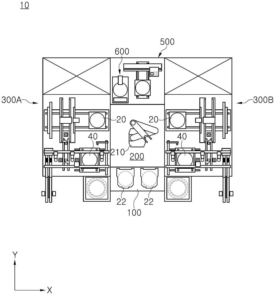
Cleaning unit, welding module and welding equipment

A technology for welding molds and air jets, applied in welding equipment, auxiliary welding equipment, welding/cutting auxiliary equipment, etc., can solve the problems of cleaning efficiency decline, insufficient removal and prevention of pollutants, etc., and achieve the effect of improving cleaning efficiency

Pending Publication Date: 2022-06-03
SEMES CO LTD
View PDF0 Cites 0 Cited by
  • Summary
  • Abstract
  • Description
  • Claims
  • Application Information

AI Technical Summary

Problems solved by technology

[0005] However, in the conventional blower, since the gas injection port and the suction port are all formed on the surface facing the substrate, the contaminants separated from the substrate or die by the cleaning gas are likely to be unable to be sucked into the suction port and become suspended.
After the cleaning process, the contaminants that could not be sucked into the suction port may be suspended and land again on the parts constituting the substrate or die bonding device, so the cleaning efficiency may decrease
Similarly, if the substrate support member on which the substrate is placed is not carefully managed, the contaminants that once existed in the substrate support member will land on the substrate or the components of the die bonding device, and the cleaning efficiency may decrease.
[0006] In addition, the general air blower is fixedly provided on the upper side of the substrate, so it is not enough to effectively remove the pollutants throughout the entire substrate and prevent the re-attachment of the removed foreign matter

Method used


Image

  • Cleaning unit, welding module and welding equipment
  • Cleaning unit, welding module and welding equipment
  • Cleaning unit, welding module and welding equipment

Examples


Embodiment Construction

[0065] Hereinafter, the embodiments of the present invention will be described in detail with reference to the accompanying drawings so that those having ordinary knowledge in the technical field to which the present invention pertains can be easily implemented. However, the present invention may be implemented in various different ways and is not limited to the embodiments described herein.

[0066] In the description of the embodiments of the present invention, when it is judged that the specific description of the related well-known functions or structures may unnecessarily obscure the gist of the present invention, the specific description is omitted, and the parts that perform similar functions and functions are described in The same reference numerals are used throughout the drawings.

[0067] At least a part of the terms used in the specification are defined in consideration of the functions in the present invention, and therefore may vary depending on the user, the ope...


PUM


Abstract

The invention discloses a cleaning unit, a welding module and welding equipment. According to one embodiment of the present invention, there can be provided a cleaning unit comprising: a gas injection unit that is disposed above an object to be cleaned and that injects gas obliquely toward the object in order to separate contaminants on the object from the object; and a suction unit which is provided on one side of the air blowing unit and includes a suction port for sucking and removing the contaminant separated from the object by the air blowing unit.

Description

technical field [0001] The present invention relates to a cleaning unit for cleaning a substrate or a substrate support member on which a substrate is placed, and a substrate processing apparatus including the same. Background technique [0002] Generally, a semiconductor element can be formed on a silicon wafer serving as a semiconductor substrate by repeatedly performing a series of manufacturing processes. The wafer on which the semiconductor element is formed can be divided into a plurality of dies by a dicing process, and the singulated die by the dicing process can be welded to a substrate such as a lead frame by a die bonding process. [0003] When the die is soldered to the substrate, if particles adhere to the surface of the substrate, there is a high probability of quality defects such as a drop in adhesion. Therefore, it is very important to remove the particles during the soldering process. Because particles of size 5 to 10 μm can also be the cause of cavities i...

Claims


Application Information

Patent Timeline
Patent Type & Authority Applications(China)
IPC IPC(8): B23K37/00B23K37/02B08B5/02
CPCB23K37/00B23K37/0247B23K37/0252B08B5/02H01L21/67028H01L21/67144B08B5/04H01L22/30H01L21/67034
Inventor 林锡泽
Owner SEMES CO LTD
Learn More