
Electronic flow float

A flowing water and electronic technology, applied in the field of fishing tackle, can solve problems such as uneven force, floating body rupture, bumping, etc., and achieve the effect of simple manufacturing process, wide application range and high durability

Pending Publication Date: 2022-06-03
何娟
View PDF5 Cites 0 Cited by
  • Summary
  • Abstract
  • Description
  • Claims
  • Application Information

AI Technical Summary

Problems solved by technology

If there is wind during fishing, the part of the water surface may be affected by the wind, causing the line group to shift and affect fishing; if there is water flow, the part below the water surface may be impacted by the water flow, which may cause the float to tilt at a large angle and affect fishing, or even the entire float will be submerged by the water flow. Underwater, in this case, the float will not work properly
The currently widely used and highly sensitive floats are vertical floats, which generally have a popular structure such as floating feet, floating bodies, and floating tails. The floating feet are generally made of carbon fiber and other materials, and the floating body is generally made of Balsewood or foam plastic. The floating tail is generally made of optical fiber. Due to the different materials of different parts, the connection between the floating feet and the floating body and between the floating body and the floating tail becomes the weak point of the strength of the entire floating. , and it is difficult to guarantee its reliability; vertical floats are generally long in size, and need to be carefully stored with a special float tube or float box, otherwise they are easily damaged, and the reason for the float material often occurs during use. The floating body is broken due to uneven force during the pole process, and the floating body is broken, which makes the whole float unusable

Method used


Image

  • Electronic flow float
  • Electronic flow float
  • Electronic flow float

Examples


Embodiment Construction

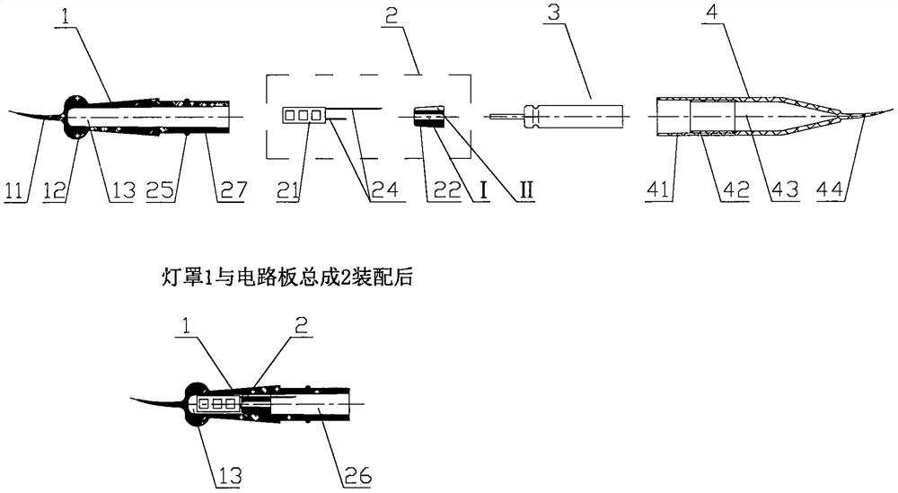
[0026] Figure 1Shown, is a schematic diagram of the decomposition structure of an electronic flow drift example I, the structure of which is mainly divided into four parts: lampshade 1, circuit board base assembly 2, pin battery 3, back cover 4. The lampshade 1 is a housing made of a transparent material, one end of which has a foot 11, can be inserted into the drift seat in the fishing line set to achieve a connection, the other end has a sealing surface 14 used for connection, may form a sealing connection with the sealing surface 23 on the circuit board assembly 2, the internal circuit board compartment 13 can accommodate a miniature intelligent circuit board 21, the outside has a spot cap 12; The circuit board seat assembly 2 is composed of a miniature intelligent circuit board 21, mount 22, electrode 24, sealing ring 25, the mount 22 is made of plastic and integrated electrode 24 inside, electrode 24 is connected to the micro intelligent circuit board 21 at its end, one end ...


PUM


Abstract

The invention discloses an electronic flow float, which relates to the field of fishing tackles for fishing and structurally comprises a lampshade, a circuit board seat assembly, a needle type battery and a rear cover. The electronic flow float lampshade, the mounting seat and the rear cover can be made of plastics with higher strength and are firm and durable, and the electronic flow float is connected to a fishing line group, is positioned above the water surface for fishing and is not in contact with water in the use process, so that the electronic flow float cannot be impacted by water flow in the fishing process, and the service life of the electronic flow float is prolonged. The influence of water flow on the whole fishing line set is very small, the fishing line set can be used in still water and running water environments, and by means of a miniature intelligent circuit board in the electronic flow float, the adaptability is higher while the sensitivity is guaranteed. The sensor is small in size, high in sensitivity, simple in process, firm, durable and high in adaptability.

Description

Technical field [0001] The present invention relates to the field of fishing gear for fishing, specifically refers to an electronic flowing water drift. Background [0002] Fishing is a kind of leisure and entertainment activities, and the current floating can be roughly divided into vertical floating, horizontal floating, spherical floating and line floating. However, no matter what kind of floating, in the normal use process, part of the fish float needs to be placed in the water, and the other part is above the water surface in order to observe the fish's bait-eating action. If there is wind during the fishing process, the surface part of the water may be affected by the wind, causing the line group to have a displacement effect on the fishing; If there is a current, the part below the surface of the water that is affected by the current may cause the fish to drift at a large angle to tilt and affect the fishing, and even the water flow will cause the entire fish to float into...

Claims


Application Information

Patent Timeline
Patent Type & Authority Applications(China)
IPC IPC(8): A01K93/02
CPCA01K93/02
Inventor 何娟
Owner 何娟
Learn More