
Low-phase noise frequency source circuit and implementation method

An implementation method and frequency source technology, applied in the field of radio frequency and microwave, can solve the problems of difficult to achieve low spurious frequency output, poor spurious performance of DDS chip output, difficult debugging, etc., to speed up phase adjustment time and speed up frequency output Good time and spurious suppression effect

Pending Publication Date: 2022-05-31
成都威频科技有限公司
View PDF2 Cites 0 Cited by
  • Summary
  • Abstract
  • Description
  • Claims
  • Application Information

AI Technical Summary

Problems solved by technology

[0004] Prior art CN112290942A discloses an ultra-fast ultra-bandwidth low-noise band-agile frequency source. Although a low-phase-noise frequency source is realized, it is difficult to achieve low Spurious frequency output; the prior art CN207490869U discloses an ultra-low phase noise frequency source circuit, which optimizes the phase noise of the signal by eliminating related phase noise. Although the phase noise can be optimized, the circuit has a complex structure and is difficult to debug. And can only output some fixed point frequency

Method used


Image

  • Low-phase noise frequency source circuit and implementation method
  • Low-phase noise frequency source circuit and implementation method
  • Low-phase noise frequency source circuit and implementation method

Examples


Embodiment 1

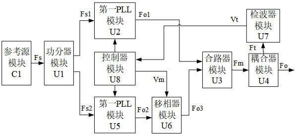
[0051] A low phase noise frequency source circuit provided by this embodiment includes a reference source module, a power divider module U1, a PLL module, a phase shifter module, a combiner module, a coupler module, a detector module, a controller module, and the like .

[0052] Specifically, as image 3 As shown, the output end of the reference source module C1 is connected to the input end of the power divider module U1, and the power divider module U1 has two output ends, which are the first output end and the second output end.

[0053] There are two PLL modules in total, namely the first PLL module U2 and the second PLL module U5, the first output end of the power divider module U1 is connected to the input end of the first PLL module U2, and the second The output terminal is connected to the input terminal of the second PLL module U5. The controller module is connected to the first PLL module and the second PLL module, respectively.

[0054] The combiner module U3 has...

Embodiment approach

[0075] As a preferred implementation, in the embodiment, two PLL modules may be DAC modules, the first PLL module may be replaced by a first DAC module, and the second PLL module and the phase shifter module may be replaced by a second DAC module, wherein The DAC module can choose a high-speed DAC that can adjust the phase function, such as Figure 5As shown, the first DAC module U2 and the second DAC module U5 are respectively connected to the two output branches of the power divider module U1; the controller module U8 is respectively connected to the first DAC module U2 and the second DAC module U5, The frequency control word and the phase control word are used to enable the first DAC module U2 and the second DAC module U5 to process the respective branch signals respectively, so that the frequencies and phases of the output signals of the first DAC module U2 and the second DAC module U5 are equal. . Due to the different delays of the transmission lines, when reaching the c...


PUM


Abstract

The invention provides a low-phase-noise frequency source circuit and an implementation method. The circuit comprises a power divider module, a first PLL module, a second PLL module, a phase shifter module, a combiner module, a coupler module and a detector module, wherein the first PLL module and the second PLL module are respectively connected with two paths of outputs of the power divider module; the phase shifter module is connected with the second PLL module; the combiner module is connected with the first PLL module and the phase shifter module; and a controller module connected with the detector module, wherein the controller module is connected with the first PLL module, the second PLL module and the phase shifter module. The phase of the output signal of the second PLL module is adjusted through the detector module, the controller module and the phase shifter module until the phase difference between the output signal of the first PLL module and the adjusted output signal of the phase shifter module reaches the combiner module is zero. According to the scheme, a lower phase noise index is achieved, the phase adjustment time can be shortened, the phase difference can be rapidly adjusted to be zero, and the frequency output time is shortened.

Description

technical field [0001] The invention relates to the technical field of radio frequency microwaves, in particular to a low phase noise frequency source circuit and an implementation method. Background technique [0002] The frequency source is the core device in modern RF microwave components, and the quality of the output signal determines the performance of the system. For example, in the precise positioning of missile guidance and satellite communication, the accuracy requirements are very high, and the frequency source requires very high stability. Secondly, the frequency source provides local oscillator signals for various receivers, participates in spectrum shifting, and also serves as a reference for the signal processor, providing it with a clock signal. Therefore, its performance indicators play a decisive role in the entire working system. [0003] Phase noise is one of the most important indicators of modern frequency sources. Low phase noise means that the baseb...

Claims


Application Information

Patent Timeline
Patent Type & Authority Applications(China)
IPC IPC(8): H03L7/22H03L7/00
CPCH03L7/22H03L7/00
Inventor 刘国超刘畅王明
Owner 成都威频科技有限公司
Learn More