Mixer assembly

A mixer and assembly technology, applied in the direction of machines/engines, charging systems, combustion engines, etc., can solve the problems of large differences in the air-fuel ratio of the mixed gas in each cylinder of the engine, uneven mixing of various gases, and reduced engine performance. , to achieve the effect of ensuring the uniformity of the concentration, preventing the discharge from exceeding the standard, and improving the compactness

Pending Publication Date: 2022-05-31
GUANGXI YUCHAI MASCH CO LTD
View PDF0 Cites 0 Cited by
  • Summary
  • Abstract
  • Description
  • Claims
  • Application Information

AI Technical Summary

Problems solved by technology

[0003] The purpose of the present invention is to provide a mixer assembly to solve the problem of uneven mixing of various gases in the existing mixer assembly, which leads to large differences in the air-fuel ratio of the mixture gas in each cylinder of the engine, which affects the combustion effect and reduces engine performance. , excessive emissions and other issues

Method used


Image

  • Mixer assembly
  • Mixer assembly
  • Mixer assembly

Examples


Embodiment 1

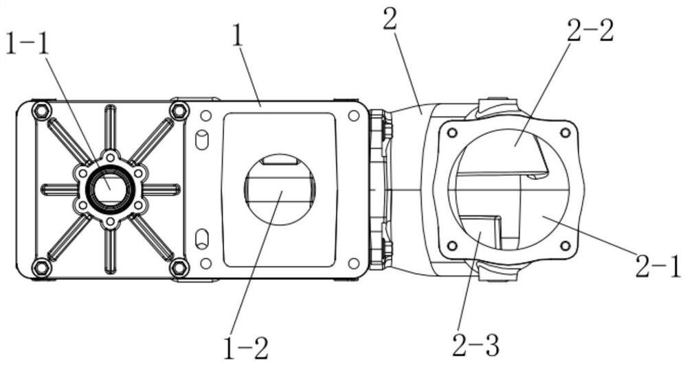
[0031] Example 1: as Figure 1-4 As shown in the figure, a mixer assembly includes a mixer 1. A mixer pipe is provided on the mixer 1. The mixer pipe runs through the left end face and the right end face of the mixer 1. The pipe opening on the left end face of the mixer 1 is Mixed gas outlet, the pipe port on the right end face of the mixer 1 is the mixed gas inlet, the front end face of the mixer 1 is provided with two air inlets, the air inlet on the right side of the front end face of the mixer 1 is the EGR inlet 1-2, The air inlet on the left side of the front end face of the mixer 1 is the gas inlet 1-1, the right end face of the mixer 1 is provided with a mixer nozzle, and the mixer nozzle is provided with a flow guide structure.

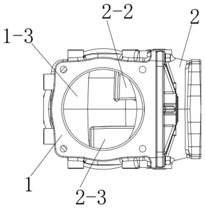
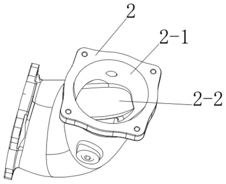
[0032] The mixer nozzle is the elbow mixer nozzle 2, the bottom surface of the bending part inside the elbow mixer nozzle 2 is provided with a vertical lower guide structure 2-3, and the bending part inside the elbow mixer nozzle 2-3 The top ...

Embodiment 2

[0033] Example 2: as Figure 2-6 As shown, in this embodiment, the structure of the mixer is the same as that of Embodiment 1, wherein the mixer nozzle is a straight-tube mixer nozzle 3, and the interior of the straight-tube mixer nozzle 3 is provided with several sidewall guide structures 3-1 , the side wall guide structure 3-1 is a blade structure, and the side wall guide structure 3-1 is reduced from the right end to the left end to form an elongated blade structure.

[0034] A rotating fan blade can also be arranged in the nozzle of the mixer.

[0035] Working principle: Before the air takes over from the mixer to enter the mixer 1, the air passes through the upper diversion structure 2-2 and the lower diversion structure 2-3 or the side wall diversion structure 3-1 to disturb the disturbance. In the mixer 1, the EGR inlet 1- The EGR exhaust gas is introduced into 2 places, and the gas is introduced into the gas inlet 1-1. When the air reaches the mixer 1, it is in a turb...


PUM


Abstract

The mixer assembly comprises a mixer, a mixer pipeline is arranged on the mixer, the mixer pipeline penetrates through the left end face and the right end face of the mixer, two air inlets are formed in the front end face of the mixer, a mixer connecting pipe is arranged on the right end face of the mixer, and a flow guide structure is arranged on the mixer connecting pipe. According to the invention, gas can be effectively guided, so that the gas can move in a specific direction, and the mixing uniformity of fuel gas and air is improved, so that the concentration uniformity of mixed gas in each cylinder of an engine is ensured; the combustion effect and the operation performance of the engine are improved, emission is reduced, and emission is prevented from exceeding the standard.

Description

【Technical field】 [0001] The invention belongs to the technical field of engine components, and in particular relates to a mixer assembly. 【Background technique】 [0002] Natural gas engine refers to an engine that uses natural gas as fuel. In recent years, natural gas engines have been widely developed and applied. Natural gas supply mode is the key technology for developing natural gas engine. It greatly affects the power, economy, safety, reliability and emission indicators of natural gas engines. The mixer is an important part of the single-point air supply natural gas engine. The mixer is installed behind the electronic throttle valve and before the intake manifold. Its function is to fully mix natural gas, intercooled air and EGR exhaust gas to make the mixed gas. The combustion is more complete, effectively reducing NOx emissions and exhaust gas temperature, thereby improving engine performance and emission targets. Due to the different densities of natural gas and...

Claims


Application Information

Patent Timeline
Patent Type & Authority Applications(China)
IPC IPC(8): F02M26/19F02M21/04
CPCF02M26/19F02M21/042F02M21/04Y02T10/30
Inventor 罗昌贵莫宗华林鹏慧魏威
Owner GUANGXI YUCHAI MASCH CO LTD
Why Eureka
Try Eureka