Self-adaptive slope compensation BOOST circuit

A slope compensation and self-adaptive technology, applied in electrical components, adjusting electrical variables, high-efficiency power electronic conversion, etc., can solve problems such as reducing transient response capability, reducing silicon utilization, reducing gain bandwidth, etc., to reduce power consumption , improve silicon utilization, and reduce the capacitor area

Pending Publication Date: 2022-05-27
SHANGHAI ORIENT CHIP TECH CO LTD
View PDF0 Cites 1 Cited by
  • Summary
  • Abstract
  • Description
  • Claims
  • Application Information

AI Technical Summary

Problems solved by technology

[0014] Traditional slope compensation can be divided into one-time slope compensation and segmented slope compensation, such as figure 2 As shown, constructing a ramp signal with a fixed slope within one clock cycle can effectively suppress the sub-harmonic oscillation phenomenon, but under different duty cycles, the required ramp slope is often not a fixed value. When determining the ramp slope, it is generally When using the slope required for the maximum duty cycle, overcompensation will occur when the duty cycle is relatively small, which will reduce the gain bandwidth and greatly reduce the transient response capability
The segmented slope compensation is to construct several fixed-slope slope signals at the same time, which are applied to different duty cycles respectively. This method is not the optimal solution to solve the compensation within the range of the full duty cycle. The introduction of capacitors will greatly reduce silicon utilization

Method used


Image

  • Self-adaptive slope compensation BOOST circuit
  • Self-adaptive slope compensation BOOST circuit
  • Self-adaptive slope compensation BOOST circuit

Examples


Embodiment Construction

[0033] Below in conjunction with the drawings, preferred embodiments of the present invention are given and described in detail.

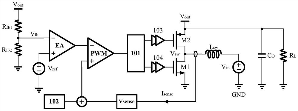
[0034] Such as image 3 As shown, the embodiment of the present invention provides a BOOST circuit with adaptive slope compensation, including a basic BOOST circuit and an adaptive slope compensation circuit 102 electrically connected to each other. The basic BOOST circuit includes power switch tube M1, synchronous rectifier tube M2, energy storage inductor L sw , the first feedback resistor R fb1 , the second feedback resistor R fb2 , Inductor current sampling circuit V sense , error amplifier EA, pulse width modulation comparator PWM, logic circuit 101, first drive buffer 103, second drive buffer 104, load resistor R L , the output capacitance C O , the first voltage source and the second voltage source, wherein the first voltage source is used to provide the input voltage V in , the second voltage source is used to provide the reference vo...


PUM


Abstract

The invention relates to a self-adaptive slope compensation BOOST circuit, which comprises a basic BOOST circuit and a self-adaptive slope compensation circuit, the basic BOOST circuit is set to receive an input voltage Vin and provide an output voltage Vout, and the self-adaptive slope compensation circuit comprises a differential circuit and a slope generation circuit, the differential circuit is configured to generate a differential current whose current magnitude is proportional to a difference between the output voltage Vout and the input voltage Vin, and the ramp generation circuit is configured to generate a sawtooth voltage whose slope is proportional to the difference between the output voltage Vout and the input voltage Vin. According to the self-adaptive slope compensation BOOST circuit, the differential circuit and the slope generation circuit are used for generating a compensation slope voltage signal which is related to input and output voltage and changes along with the duty ratio, the structure is simple, implementation is easy, and the compensation performance is good in a wide output voltage range.

Description

technical field [0001] The invention relates to the technical field of integrated circuits, in particular to a BOOST circuit with adaptive slope compensation. Background technique [0002] With the blowout development of the electronics industry, power management chips are widely used in portable devices as an extremely important voltage regulator module, which requires the chip to ensure stable and efficient working conditions under wide input and wide output voltage ranges . Compared with other types of power management chips, DC-DC converters have great advantages in conversion efficiency, especially the BOOST circuit in peak current control mode, due to its fast transient response, wide gain bandwidth, and excellent EMI characteristics. And is widely used. [0003] But the peak current control mode will appear sub-harmonic oscillation when the duty cycle is greater than 50%, such as Figure 1A with 1B As shown, ΔI 0 is the initial disturbance of the inductor current,...

Claims


Application Information

Patent Timeline
Patent Type & Authority Applications(China)
IPC IPC(8): H02M3/158H02M1/14H02M1/15
CPCH02M3/1584H02M1/143H02M1/15Y02B70/10
Inventor 不公告发明人
Owner SHANGHAI ORIENT CHIP TECH CO LTD
Why Eureka
Try Eureka