
Button cell and surface treatment process of cap of button cell

A button battery, cap technology, applied in the direction of battery cover/end cover, battery pack parts, battery box/jacket, etc., can solve the problem of battery placement space, greatly increased corrosion resistance requirements, positive electrode metal prone to electrical corrosion, energy It is difficult to increase the density and other problems, so as to achieve the effect of simple and exquisite design, reducing the volume and improving the service life.

Pending Publication Date: 2022-05-27
东莞市电的电子有限公司
View PDF0 Cites 0 Cited by
  • Summary
  • Abstract
  • Description
  • Claims
  • Application Information

AI Technical Summary

Problems solved by technology

[0003] At present, small soft-pack polymer batteries and button batteries on the market occupy a certain volume because of the structure and shell packaging, and it is difficult to improve the energy density; especially in smaller and more sophisticated equipment, the battery placement space and corrosion resistance The temperature requirement is greatly increased, because the traditional steel shell button battery produces hydrofluoric acid when there is a small amount of water in the electrolyte (a small amount of water is unavoidable), and the battery is charged under the condition of voltage and hydrofluoric acid The positive metal of the steel case button battery is extremely prone to electrical corrosion
Seriously affect the performance of the battery, including the loss of battery capacity, the increase of battery internal resistance after a period of time, the cycle performance of the battery, and the deepening of electrical corrosion, which will completely damage the battery, which directly affects the promotion and use of the battery in the field of precision equipment

Method used


Image

  • Button cell and surface treatment process of cap of button cell
  • Button cell and surface treatment process of cap of button cell
  • Button cell and surface treatment process of cap of button cell

Examples


Embodiment

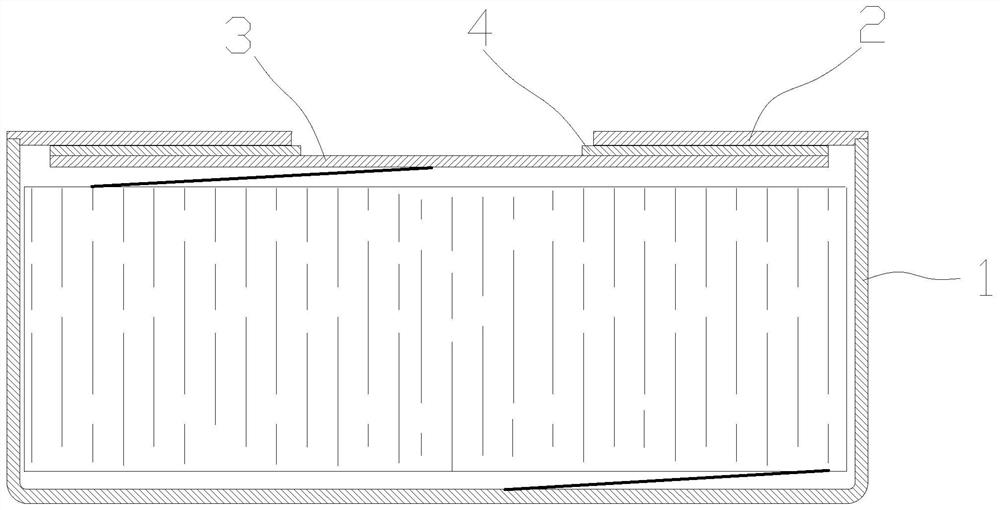
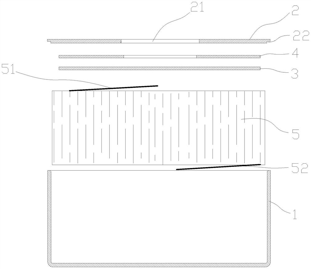
[0034] Example: Reference Figure 1-3 , the present invention mainly aims at some problems such as small capacity or specific energy density of the existing button battery, no explosion-proof function, poor corrosion resistance, short service cycle, etc., and provides a button battery, such as figure 1 As shown, the button battery includes a shell 1 with a bottom surface and a side wall extending around the edge of the bottom surface. The shell 1 is made of stainless steel. In this embodiment, the shell 1 is a cylindrical structure with an open upper end, and the single-wall thickness is 0.1 --0.25mm, the upper edge of the shell 1 is connected with a cap to form a hollow cavity.

[0035] The cap includes a connecting ring 2 with a through hole 21 in the middle and an electrode sheet 3 connected to the surface wall of the connecting ring 2 through a sealing insulating glue 4 and used to cover the through hole 21. The connecting ring 2 is welded with the upper edge of the casing...


PUM

PropertyMeasurementUnit
thicknessaaaaaaaaaa
thicknessaaaaaaaaaa
elongation at breakaaaaaaaaaa

Abstract

The invention discloses a button cell and a surface treatment process of a cap of the button cell, and relates to the technical field of microcells. The shell is provided with a bottom surface and a side wall extending around the edge of the bottom surface, the edge of the upper end of the shell is connected with a cap, and the cap comprises a connecting ring with a through hole in the middle and an electrode plate which is connected to the surface wall of the connecting ring through sealing insulation glue and used for covering the through hole. The connecting ring is welded with the edge of the upper end of the shell; an electrode assembly and electrolyte are arranged in the shell, one side of the electrode assembly is electrically connected to the inner wall of the shell through a conductor, and the other side of the electrode assembly is electrically connected with the electrode plate through a conductor. The button cell is simple and exquisite in structural design, low in manufacturing cost, capable of improving the capacity and specific energy density of the button cell, good in sealing performance, anti-explosion performance and corrosion resistance, long in storage time and long in service life.

Description

technical field [0001] The invention relates to the technical field of miniature batteries, in particular to a surface treatment process for a button battery and its cap. Background technique [0002] With the development of electronic technology, microelectronic technology and modern smart wearable devices, the market continues to increase the power supply requirements for electronic devices, which tend to be miniaturized and have higher energy density; at the same time, the devices are also required to be portable and have better battery life. Experience, such as wireless TWS Bluetooth headsets, hearing aids, electronic gastroscopes, 3D glasses, etc., requires both miniaturization and light weight of the product, and also needs to meet the battery life of the power supply, so higher requirements are placed on the size and quality of the battery. [0003] At present, small soft-pack polymer batteries and button batteries on the market occupy a certain volume in structure an...

Claims


Application Information

Patent Timeline
Patent Type & Authority Applications(China)
IPC IPC(8): H01M50/109H01M50/143H01M50/145H01M50/147H01M50/171H01M50/188
CPCH01M50/109H01M50/147H01M50/171H01M50/143H01M50/145H01M50/188Y02P70/50
Inventor 廖建华邬永缜
Owner 东莞市电的电子有限公司
Learn More