


Quick Research
Generate reliable direction feasibility study reports for your R&D in just a few steps.

Technical Q&A
Discover and master advanced knowledge NOW. Basics, ideas, possibilities, all at once.

Find Solutions
As an expert in R&D theories, this can generate solutions to your technical problems instantly.

Evaluate Feasibility
Analyze your overall solution with one click, know your potential R&D risks in advance.

Monitor Landscape
Get weekly tech updates, stay abreast of the latest tech innovations and key insights.
Anti-vibration and anti-shake base for automatic feeding robot of die casting machine
A technology for robots and die-casting machines, which is applied in the directions of supporting machines, engine frames, and manipulators.
- Summary
- Abstract
- Description
- Claims
- Application Information
AI Technical Summary
Problems solved by technology
Method used
Image

Examples
Embodiment 1
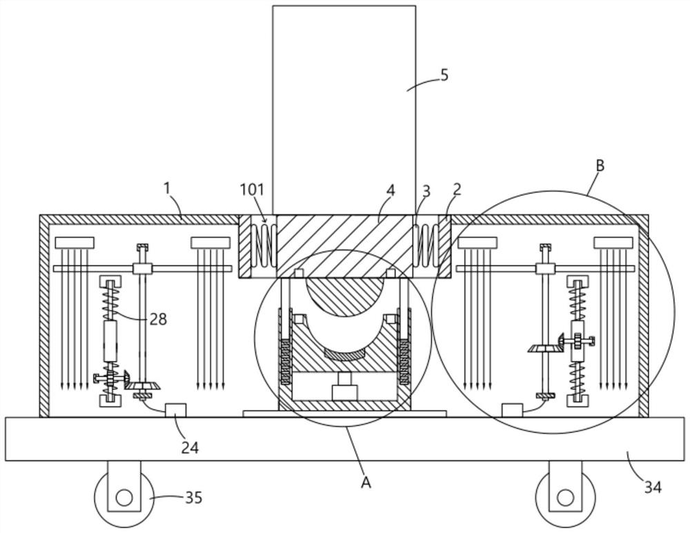
[0030] An anti-vibration and anti-shake base for an automatic feeding robot of a die-casting machine, comprising a base shell 1, a buffer groove 101 is opened in the base shell 1, and both ends of the buffer groove 101 are provided with anti-collision flexible pads 2 to prevent collision. The arrangement of the flexible pad 2 can prevent the mobile base 4 from bumping hard during lateral buffering. The anti-collision flexible pad 2 is connected with a shock-absorbing spring 3 , and the end of the shock-absorbing spring 3 away from the anti-collision flexible pad 2 is connected to the mobile base 4 . Above, the mobile base 4 is fixedly provided with a feeding robot main body 5 .
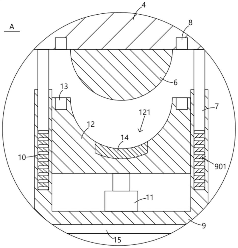
[0031] The bottom of the movable base 4 is fixedly provided with an arc-shaped block 6 and a plug-in plate 7, and a magnetic block 8 is embedded in the side of the movable base 4 with the arc-shaped block 6, and a plurality of magnetic blocks 8 can be provided, thereby improving the magnetic attraction...
Embodiment 2
[0035] The base shell 1 is provided with a buffer groove 101 , both ends of the buffer groove 101 are provided with an anti-collision flexible pad 2 , and a shock-absorbing spring 3 is connected to the anti-collision flexible pad 2 , and the shock-absorbing spring 3 is far from the anti-collision flexible pad 2 . Both ends are connected to the mobile base 4, and the mobile base 4 is fixedly provided with a feeding robot main body 5.
[0036] The bottom of the movable base 4 is fixedly provided with an arc block 6 and an insert plate 7. There are two insert plates 7, and they are symmetrically arranged on both sides of the arc block 6. Therefore, the force of the mobile base 4 is also more uniform, avoiding tilting. A magnetic block 8 is embedded in the side of the movable base 4 where the arc-shaped block 6 is arranged, an open box 9 is arranged below the arc-shaped block 6, and a groove 901 is opened on the side wall of the open box 9. The bottom of the groove 901 is connecte...
Embodiment 3
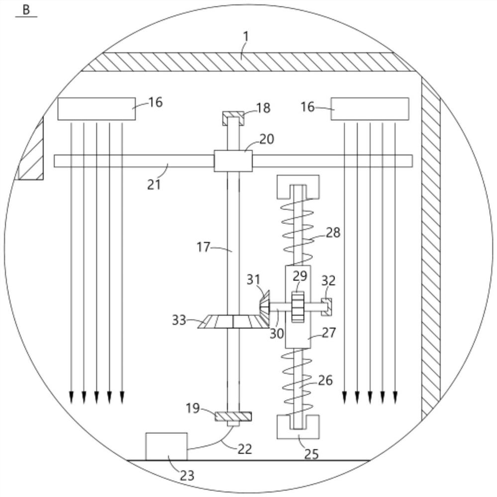
[0040] This embodiment further defines and discloses the structure of the transmission device on the basis of the above-mentioned first and second embodiments: the transmission device includes a gear 29, and the gear 29 can be driven to rotate by the rack slide 27, and the gear 29 is rotated. A rotating rod 30 is fixedly arranged in the center, one end of the rotating rod 30 is fixedly provided with a driving bevel gear 31, and the rotating rod 30 is fixed at the center position of the non-gear surface of the driving bevel gear 31, and the rotating rod 30 is away from the driving bevel gear 31. One end is hingedly arranged in the bearing base 32, and the bearing base 32 is fixedly arranged inside the moving base 4, so that the rotating rod 30 can be smoothly rotated in place, and the side of the driving bevel gear 31 is meshed with a passive bevel gear 33, which is driven by The bevel gear 33 is an insulator, and the driven bevel gear 33 is fixedly sleeved on the conductive rod...
PUM
 Abstract
Description
Claims
Application Information
 - R&D Engineer
- R&D Manager
- IP Professional
- Industry Leading Data Capabilities
- Powerful AI technology
- Patent DNA Extraction
Browse by: Latest US Patents, China's latest patents, Technical Efficacy Thesaurus, Application Domain, Technology Topic, Popular Technical Reports.
© 2024 PatSnap. All rights reserved.Legal|Privacy policy|Modern Slavery Act Transparency Statement|Sitemap|About US| Contact US: help@patsnap.com