Industrial robot automatic detection obstacle avoidance control method
An industrial robot and control method technology, applied in the direction of comprehensive factory control, program control manipulator, manipulator, etc., can solve the problems of low degree of intelligence, inability to achieve large-scale, three-dimensional and all-round detection, and limited sensor detection range, etc. To achieve the effect of improving intelligence and autonomy
- Summary
- Abstract
- Description
- Claims
- Application Information
AI Technical Summary
Problems solved by technology
Method used
Image

Examples
Embodiment 1
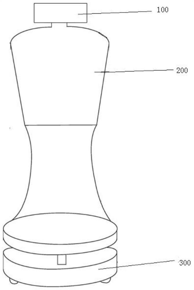
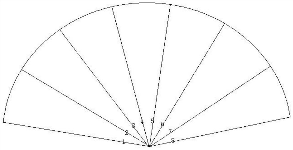
[0034] like figure 1 As shown, the main components of the industrial robot in this embodiment are the head 100 , the torso 200 and the chassis 300 , and the head 100 , the torso 200 and the chassis 300 are all equipped with sensor modules, thereby realizing the detection of obstacles of different heights. to increase the detection accuracy of obstacle avoidance, and the sensor modules of the head 100, the torso 200 and the chassis 300 have the same structure and configuration, as shown in figure 2 As shown, each sensor module is composed of 8 sensors numbered 1-8, and the detection angle of each sensor is 20-30° (preferably 25°), and the 8 sensors of each sensor module are The detection ranges are connected in sequence to form a fan-shaped detection area; in this embodiment, the sensor is an infrared sensor;
[0035] At the same time, the sensor module signals of the three positions of the head 100, the torso 200 and the chassis 300 have the same priority, and a single trigg...
Embodiment 2
[0055] The difference between this embodiment and Embodiment 1 is that the sensor in this embodiment is a microwave sensor, and when a microwave sensor is used, the time point when the microwave sensor detects wave emission is denoted as T 0 , after the detection wave of the microwave sensor is emitted, it is reflected back to the sensor when it encounters an obstacle, and the moment when the sensor receives the detection wave is T 1 ;
[0056] Obtain the distance X between the industrial robot and the obstacle by calculating formula (1) 0 :
[0057]
[0058] Among them, the motion speed of the industrial robot when the detection wave of the microwave sensor is emitted is V 0 ;
[0059] Get the current travel speed V of the industrial robot in real time 1 , then pass the distance X between the industrial robot and the obstacle 0 with the speed V of current industrial robots 1 Obtained pre-collision time T=X 0 / V 1 .
Embodiment 3
[0061] The difference between this embodiment and Embodiment 1 or 2 is that the controller is further provided with a state detection unit for monitoring the operation parameters of the industrial robot, wherein the operation parameters include temperature, feedback duration and Maintenance records, etc., the temperature is the internal temperature of the industrial robot when it is working, the feedback duration is the time interval from when the industrial robot receives the obstacle avoidance control signal to the execution of the obstacle avoidance action, and the maintenance record is the predetermined time (such as within one month) of the industrial robot. The total number of maintenance, thereby extending the service life of the industrial robot by monitoring the operating parameters of the industrial robot.
[0062] To sum up, in the present invention, sensor modules are arranged on the head, torso and chassis of the industrial robot, and the sensors in each sensor mod...
PUM
 Abstract
Description
Claims
Application Information
 - R&D
- Intellectual Property
- Life Sciences
- Materials
- Tech Scout
- Unparalleled Data Quality
- Higher Quality Content
- 60% Fewer Hallucinations
Browse by: Latest US Patents, China's latest patents, Technical Efficacy Thesaurus, Application Domain, Technology Topic, Popular Technical Reports.
© 2025 PatSnap. All rights reserved.Legal|Privacy policy|Modern Slavery Act Transparency Statement|Sitemap|About US| Contact US: help@patsnap.com