
Magnetic box cleaning machine and manufacturing method and using method thereof

A production method and cleaning machine technology, which are applied in the directions of manufacturing tools, grinding frames, grinding machine parts, etc., can solve the problems of affecting the fixing effect of the magnetic box, the unevenness of the adsorption bottom surface, affecting the grinding, etc., so as to achieve ingenious design, The effect of uniform grinding and reducing failure

Active Publication Date: 2022-05-27
宁波赛鑫磁性技术有限公司
View PDF8 Cites 0 Cited by
  • Summary
  • Abstract
  • Description
  • Claims
  • Application Information

AI Technical Summary

Problems solved by technology

Due to the particularity of the magnetic box itself, there are magnet components with strong magnetism. During operation, the parts that come with the manual grinder are easily attracted by the magnetic box, which affects the grinding. In addition, manual grinding is not only inefficient, but also has human factors. After the adsorption bottom surface is polished, it is prone to unevenness, which directly affects the fixing effect of the magnetic box

Method used


Image

  • Magnetic box cleaning machine and manufacturing method and using method thereof
  • Magnetic box cleaning machine and manufacturing method and using method thereof
  • Magnetic box cleaning machine and manufacturing method and using method thereof

Examples


Embodiment Construction

[0038] The technical solutions in the specific embodiments of the present invention will be clearly described below with reference to the accompanying drawings. Obviously, the described embodiments are part of the embodiments of the present application, but not all of the embodiments. Those of ordinary skill in the art are inspired by the following examples, and all other examples obtained belong to the protection scope of the present invention.

[0039] The terms "first", "second" and the like in the description and claims of the present application are used to distinguish similar objects, and are not used to describe a specific order or sequence. It is to be understood that the data so used are interchangeable under appropriate circumstances so that the embodiments of the present application can be practiced in sequences other than those illustrated or described herein, and distinguish between "first", "second", etc. The objects are usually of one type, and the number of obj...


PUM


Abstract

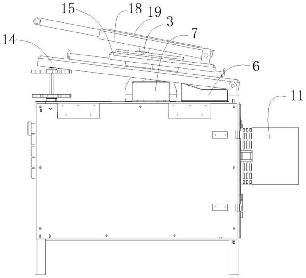
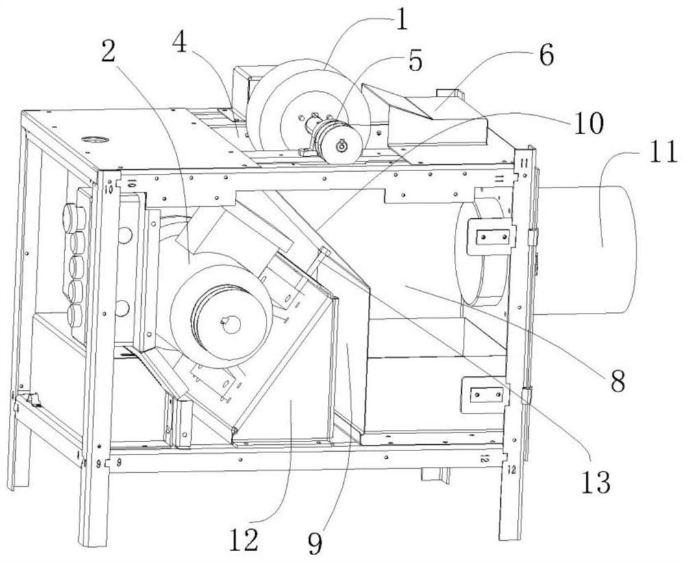
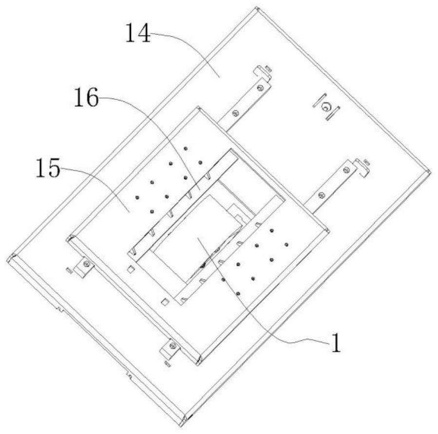
A magnetic box cleaning machine comprises a polishing mechanism which achieves cleaning of the adsorption bottom face of a workpiece through a polishing wheel; the driving device drives the polishing wheel to rotate; the rack assembly comprises a box body and a workpiece loading table which can be pivotally opened at the top of the box body, one end of the workpiece loading table is pivotally connected to the box body, the other end of the workpiece loading table is suspended and supported on the box body, a containing hole is formed in the top of the box body to contain the polishing wheel, and a workpiece is loaded on the workpiece loading table and moves back and forth on the polishing wheel; in the back-and-forth moving process, the adsorption bottom surface is in press contact with the grinding wheel; a first chamber body is formed in the box body, a closed collecting chamber is formed after the top suction opening of the first chamber body is in butt joint with the containing hole so as to receive and collect dust and impurities generated in the cleaning process, the remaining space in the box body forms a component mounting chamber independent of the first chamber body, and the cleaning machine has the advantages of being efficient, smooth in cleaning and even in cleaning. On the basis, the invention further provides a manufacturing and using method of the magnetic box cleaning machine.

Description

technical field [0001] The invention relates to the technical field of magnetic box cleaning, in particular to a magnetic box cleaning machine and a method for making and using the same. Background technique [0002] The magnetic box refers to a magnetic fixing device that fixes the molds used to produce the prefabricated concrete components on the working mold table during the production process of the prefabricated concrete components. The magnetic fixing device includes a casing, the casing is provided with an installation cavity, the installation cavity is provided with a magnet assembly that can be driven, the casing is provided with a magnetic switch for driving the magnet assembly to move up and down, and One end of the bottom edge of the casing is provided with a limit groove to cooperate with the template of the mold, so that when the mold needs to be fixed, the peripheral part of the limit groove is pressed against the template, and then the magnetic switch is pres...

Claims


Application Information

Patent Timeline
Patent Type & Authority Applications(China)
IPC IPC(8): B24B27/033B24B41/02B24B41/06B24B47/12B24B47/16B24B55/06B24B55/12
CPCB24B27/033B24B41/02B24B47/12B24B41/06B24B47/16B24B55/06B24B55/12
Inventor 谢琨辉
Owner 宁波赛鑫磁性技术有限公司
Learn More