
Purifying and discharging device for flue gas desulfurization and denitrification

A desulfurization, denitrification and emission device technology, which is applied in gas treatment, transportation and packaging, and air quality improvement, etc., can solve the problems of being used, cannot absorb liquid, and reduce the working efficiency of flue gas desulfurization and denitrification, so as to improve work efficiency and reduce The effect of complexity and high denitrification rate

Inactive Publication Date: 2022-05-27
汪宣坤
View PDF0 Cites 2 Cited by
  • Summary
  • Abstract
  • Description
  • Claims
  • Application Information

AI Technical Summary

Problems solved by technology

[0003] When the existing equipment desulfurizes and denitrates the flue gas, the solution absorption method is often used in the purification treatment stage. However, the current method generally directly passes the flue gas into the solution, which easily saturates the absorption liquid partially, resulting in the absorption liquid cannot It is utilized to the greatest extent, so that the resources of the absorption liquid are wasted; at the same time, the desulfurization process and the denitrification process are processed in stages, which increases the complexity of the equipment and reduces the work efficiency of flue gas desulfurization and denitrification

Method used


Image

  • Purifying and discharging device for flue gas desulfurization and denitrification
  • Purifying and discharging device for flue gas desulfurization and denitrification
  • Purifying and discharging device for flue gas desulfurization and denitrification

Examples


Embodiment Construction

[0035] The technical solutions in the embodiments of the present invention will be clearly and completely described below with reference to the accompanying drawings in the embodiments of the present invention. Obviously, the described embodiments are only a part of the embodiments of the present invention, rather than all the embodiments. Based on the embodiments of the present invention, all other embodiments obtained by those of ordinary skill in the art without creative efforts shall fall within the protection scope of the present invention.

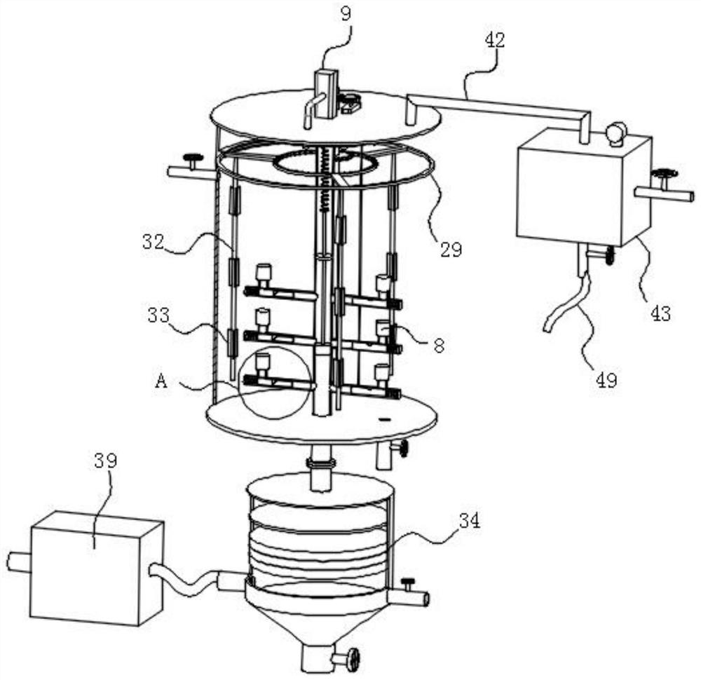
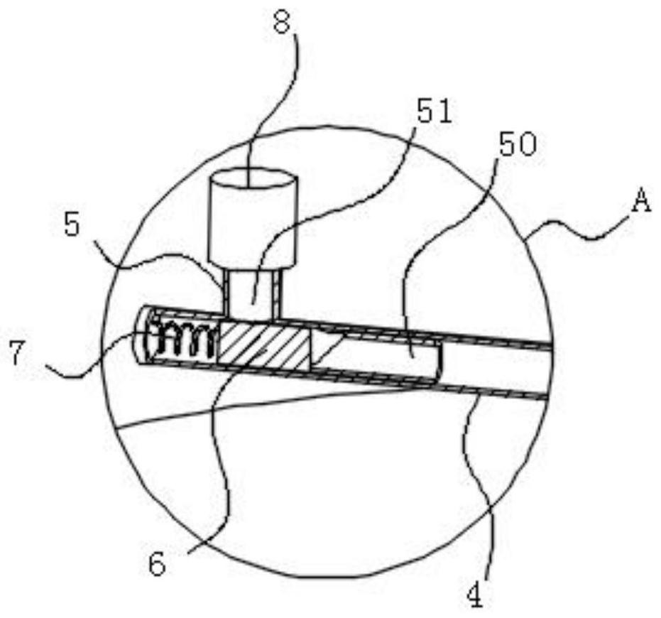
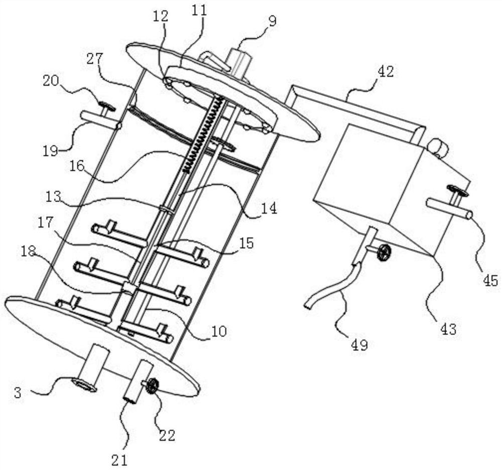
[0036] see Figure 1-8 As shown, the present invention is a purification and discharge device for flue gas desulfurization and denitrification, comprising a filter assembly 1 and a purification box 2; the filter assembly 1 and the purification box 2 are fixedly connected by connecting flanges; the inner top of the purification box 2 A flue gas main pipe 3 is fixedly connected, and the flue gas main pipe 3 penetrates the inner bottom ...


PUM


Abstract

The invention discloses a purification and emission device for flue gas desulfurization and denitrification, and relates to the technical field of waste gas treatment. The device comprises a filter assembly and a purification box body, a threaded pipe penetrates through the peripheral side surface of the branch pipe; sliding rods are in sliding fit with the inner walls of the branch pipes; the input end of the infusion pump is rotationally matched with a connecting pipe; an annular liquid storage box is fixedly mounted at the top in the purification box body; atomizing nozzles are distributed on the bottom face of the annular liquid storage box in a circumferential array mode. Flue gas subjected to cooling and impurity removal is introduced into a flue gas header pipe and then enters all branch pipes to extrude a sliding rod, so that an L-shaped gas inlet groove communicates with a threaded pipe, the flue gas enters a sodium hydroxide solution in a purification box, a driving motor is started to drive a connecting pipe to rotate, and therefore a stirring assembly is driven to rotate to stir absorption liquid; the purpose of uniformly mixing the absorption liquid is achieved; clO2 is introduced into the top in the purification box body through the gas inlet pipe, NO is oxidized into NO2 by ClO2, then NO2 is reduced into N2 by using a Na2SO3 aqueous solution, and desulfurization and denitrification are synchronously carried out.

Description

technical field [0001] The invention belongs to the technical field of waste gas treatment, and in particular relates to a purification and discharge device for flue gas desulfurization and denitrification. Background technique [0002] The working principle of desulfurization and denitrification refers to reducing the generated NOX to N2, thereby removing NOX in the flue gas. According to the treatment process, it can be divided into wet denitrification and dry denitrification; mainly include: acid absorption method, alkali absorption method, Selective catalytic reduction method, non-selective catalytic reduction method, adsorption method, ion activation method, etc.; Desulfurization and denitrification are simply the process of neutralizing acid with alkali, and desulfurization is to remove sulfur dioxide contained in boiler flue gas; Out of stock is: to remove nitrogen oxides contained in boiler flue gas. [0003] When the existing equipment desulfurizes and denitrifies ...

Claims


Application Information

Patent Timeline
Patent Type & Authority Applications(China)
IPC IPC(8): B01D53/75B01D53/50B01D53/56B01D53/76B01D53/78B01D53/79B01D46/42B01D46/64
CPCB01D53/75B01D53/76B01D53/78B01D53/79B01D53/56B01D53/504B01D46/4218B01D2251/108B01D2251/20B01D2251/304B01D2251/604B01D2258/0283Y02A50/20
Inventor 汪宣坤
Owner 汪宣坤
Learn More