Wireless charging power converter and standard decoupling design method thereof

A technology of power converter and wireless charging, which is applied in the direction of conversion of AC power input to DC power output, output power conversion device, irreversible conversion of AC power input into DC power output, etc. It can solve the problem of large changes in coil coupling coefficient, The interoperability requirements are not easy to be met, and the decoupling design of the primary side coil and the secondary side coil cannot be realized, so as to achieve the effect of meeting the interoperability requirements.

Pending Publication Date: 2022-05-24
张朝辉
View PDF0 Cites 0 Cited by
  • Summary
  • Abstract
  • Description
  • Claims
  • Application Information

AI Technical Summary

Problems solved by technology

As a result, the power converter either works in the constant current mode or in the constant voltage mode, the output current, voltage or operating frequency are seriously affected by the coupling coefficient, and the decoupling design cannot be realized between the primary side coil and the secondary side coil, interoperability requirements ( i.e. versatility) is not easy to be satisfied
In the actual charging process, not only the constant current mode and constant voltage mode are required, but also the constant power mode is required, and the coupling coefficient of the coils changes greatly during interoperability and alignment.
Interoperability is an important basis for the popularization and application of wireless charging systems. The existing design schemes cannot meet the above requirements well, and technical problems need to be solved urgently.

Method used


Image

  • Wireless charging power converter and standard decoupling design method thereof
  • Wireless charging power converter and standard decoupling design method thereof
  • Wireless charging power converter and standard decoupling design method thereof

Examples


Embodiment Construction

[0058] The present invention will be described and analyzed in detail below with reference to the accompanying drawings and preferred embodiments. Obviously, the described embodiments are only some but not all of the embodiments of the present invention.

[0059] 1. Preferred embodiments of the present invention

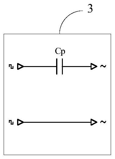
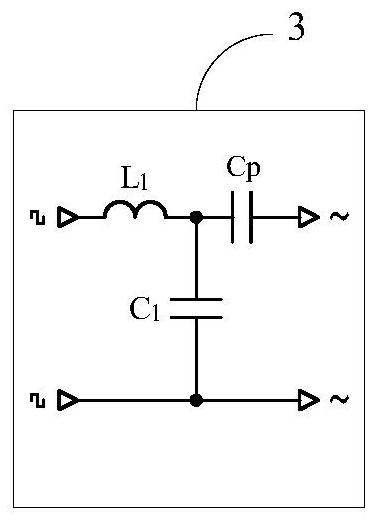
[0060] like figure 1 As shown, a wireless charging power converter and a standardized decoupling design method thereof, wherein the wireless charging power converter is composed of an APFC circuit (1), an inverter circuit (2), a primary side compensation network (3), and a coupling coil (4) ), secondary side compensation network (5), rectifier circuit (6) and filter capacitor Co. The coupling coil (4) includes a primary coil Np and a secondary coil Ns. The APFC circuit (1) is a four-terminal network, adopts a rectifier bridge+Boost conversion topology or a bridgeless Boost topology, and has two AC input ends, a positive output end, and a negative output end. The ...


PUM


Abstract

The invention relates to a wireless charging power converter and a standard decoupling design method thereof. The wireless charging power converter is composed of an APFC circuit (1), an inverter circuit (2), a primary side compensation network (3), a coupling coil (4), a secondary side compensation network (5), a rectification circuit (6) and a filter capacitor Co. The coupling coil (4) comprises a primary side coil Np and a secondary side coil Ns. And the primary side compensation network (3) adopts S compensation or LCC or CLC or LC compensation. And the secondary side compensation network (5) adopts PS compensation or CCL compensation or CL compensation or SP compensation or S compensation. And a unified analytic expression of primary and secondary coils and various compensations is given, and primary and secondary decoupling design is realized. Coil self-inductance is irrelevant to compensation topology, a primary side parameter is irrelevant to a coupling coefficient, and the primary side parameter and a secondary side parameter are relatively independent; the coupling coefficient is measured according to the ground clearance of the specific secondary side coil and a certain deviation position of the primary side coil with the same power level in the X and Y directions. The method has the advantages that soft switching frequency modulation control is achieved; (2) constant-power, constant-current and constant-voltage output can be realized; (3) large-range change of coupling coefficients is adapted; and 4, a foundation is laid for interoperability and standardization.

Description

technical field [0001] The invention relates to a wireless charging power converter and a standardized decoupling design method thereof, which is a wireless power transmission technology and belongs to the technical field of power electronics. Background technique [0002] In recent years, with the development of the new energy vehicle industry, the wireless charging technology of electric vehicles has also shown great development prospects, and has been highly valued by the industry and the country. The relevant international standards (SAE J2954, ISO 19363, IEC 61980) And the national standard has been released. On April 28, 2020, the National Standardization Administration announced a total of 4 national standards for "GB / T38775.X Electric Vehicle Wireless Charging System", which will be officially implemented on November 1, 2020. In addition, relevant standards for interoperability requirements and test methods are being developed. [0003] Most of the power converters...

Claims


Application Information

Patent Timeline
Patent Type & Authority Applications(China)
IPC IPC(8): H02M7/5387H02M7/219H02M7/25H02J7/02H02J50/12B60L53/12B60L53/22
CPCH02M7/53871H02M7/219H02M7/25H02J7/02H02J50/12B60L53/12B60L53/22Y02T10/70Y02T10/7072Y02T90/14
Inventor 张朝辉
Owner 张朝辉
Why Eureka
Try Eureka