
Valve limiting indication structure

A valve limiting and indicating technology, applied in the valve device, valve details, valve operation/release device, etc., can solve the problems of excessive driving rod application, damage activities, fusing, etc., to reduce resistance and reduce the cost of technical transformation. , cleverly designed effects

Inactive Publication Date: 2022-05-24
盐城志驰机械有限公司
View PDF0 Cites 0 Cited by
  • Summary
  • Abstract
  • Description
  • Claims
  • Application Information

AI Technical Summary

Problems solved by technology

If the driving rod of the valve limit switch is operated at an extremely slow speed, the switching of the contacts may be unstable, and a fuse may occur. If the operating speed is extremely fast, the impact force of the action may damage the switch. Do not apply excessive force to the driving rod.
May cause damage or poor activity

Method used


Image

  • Valve limiting indication structure
  • Valve limiting indication structure
  • Valve limiting indication structure

Examples


Embodiment Construction

[0019] The specific implementation manners of the present invention will be further described below in conjunction with the drawings and examples. The following examples are only used to illustrate the technical solutions of the present invention more clearly, and cannot be used to limit the protection scope of the present invention.

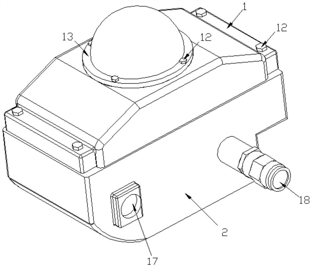
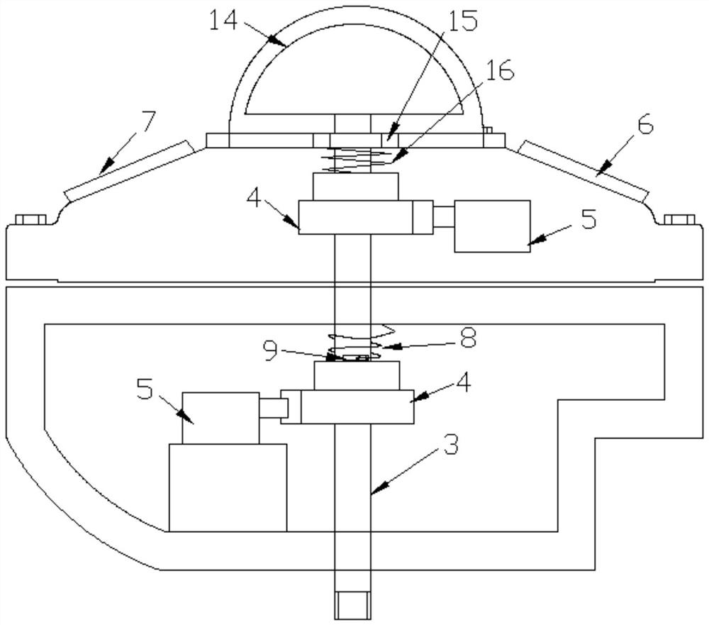
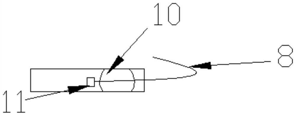
[0020] like Figure 1 to Figure 4 As shown, the present invention is a valve limit indicating structure, which includes an upper cover 1 and a main body 2 connected with the upper cover 1. A driving rod 3 is arranged inside the main body 2. The lower end of the driving rod 3 passes through the lower end of the main body 2, and the driving rod 3 is fixed with upper and lower two cams 4, and the setting position of the cams 4 corresponds to the two micro switches 5 on the main body 2, and the driving rod 3 is connected with a torsion spring 8 for avoiding the impact force generated by a quick action that may damage the switch structure. The uppe...


PUM


Abstract

The valve limiting indication structure comprises an upper cover and a main body connected with the upper cover, a driving rod is arranged in the main body, the lower end of the driving rod penetrates through the lower end of the main body, an upper cam and a lower cam are fixedly arranged on the driving rod, and the arrangement positions of the cams correspond to two microswitches on the main body; the driving rod is connected with a torsion spring structure which is used for preventing impact force generated by quick action from possibly damaging the switch. Through the arrangement of the torsion spring structure, the switch can be prevented from being damaged by impact force generated by quick action, the problem that switching of contacts is unstable when the operation speed is extremely low can also be avoided, the technical improvement degree is low, the technical improvement cost is low, two needed functions are achieved through one technical improvement point, and the design is ingenious.

Description

technical field [0001] The invention relates to a valve limit indicating structure. Background technique [0002] The valve limit switch box is a field instrument for detecting the state of the valve in the automatic control system. It is used to output the open or closed position of the valve as a signal of the switch value. The remote controller receives it or the computer searches for sampling. After confirmation, the next step is executed. This product can also be used as an important valve chain protection and remote alarm indication in the automatic control system. The valve limit switch is a field instrument for detecting the state of the valve in the automatic control system. It is used to output the open or closed position of the valve as a signal of the switch (electric shock), which is accepted by the program controller or searched and sampled by the computer. After confirmation, the next step is executed. program. It can also be used for interlock protection of...

Claims


Application Information

Patent Timeline
Patent Type & Authority Applications(China)
IPC IPC(8): F16F15/121F16K31/524
CPCF16F15/1216F16K31/524
Inventor 卢学鹏
Owner 盐城志驰机械有限公司
Learn More