Power transformer

A technology for power transformers and transformers, applied in the field of transformers, can solve the problems of slow heat dissipation of cooling oil, poor heat dissipation effect, and easy damage of oil tank heat dissipation plates and oil tank barrels, so as to achieve the effect of improving cooperation and connectivity.

Pending Publication Date: 2022-05-20
广东拓杰机电工程有限公司
View PDF0 Cites 0 Cited by
  • Summary
  • Abstract
  • Description
  • Claims
  • Application Information

AI Technical Summary

Problems solved by technology

[0004] The purpose of the present invention is to provide a power transformer to solve the problem that the cooling oil in the transformer and the cooling inside the oil tank barrel can only flow in one direction and cannot carry out two-way circulation, which makes the oil tank barrel flow to the transformer. The cooling oil circulating inside the casing dissipates heat slowly, and the heat dissipation effect is poor, which is not conducive to rapid cooling of the transformer inside the transformer casing; the oil tank barrel is placed in the open air for a long time, and the oil tank cooling plate and oil tank barrel are easily damaged. Disassembly and replacement of the overall fuel tank barrel and fuel tank cooling plate from the support plate, etc.

Method used


Image

  • Power transformer
  • Power transformer
  • Power transformer

Examples


Embodiment Construction

[0025] The following will clearly and completely describe the technical solutions in the embodiments of the present invention with reference to the accompanying drawings in the embodiments of the present invention. Obviously, the described embodiments are only some, not all, embodiments of the present invention.

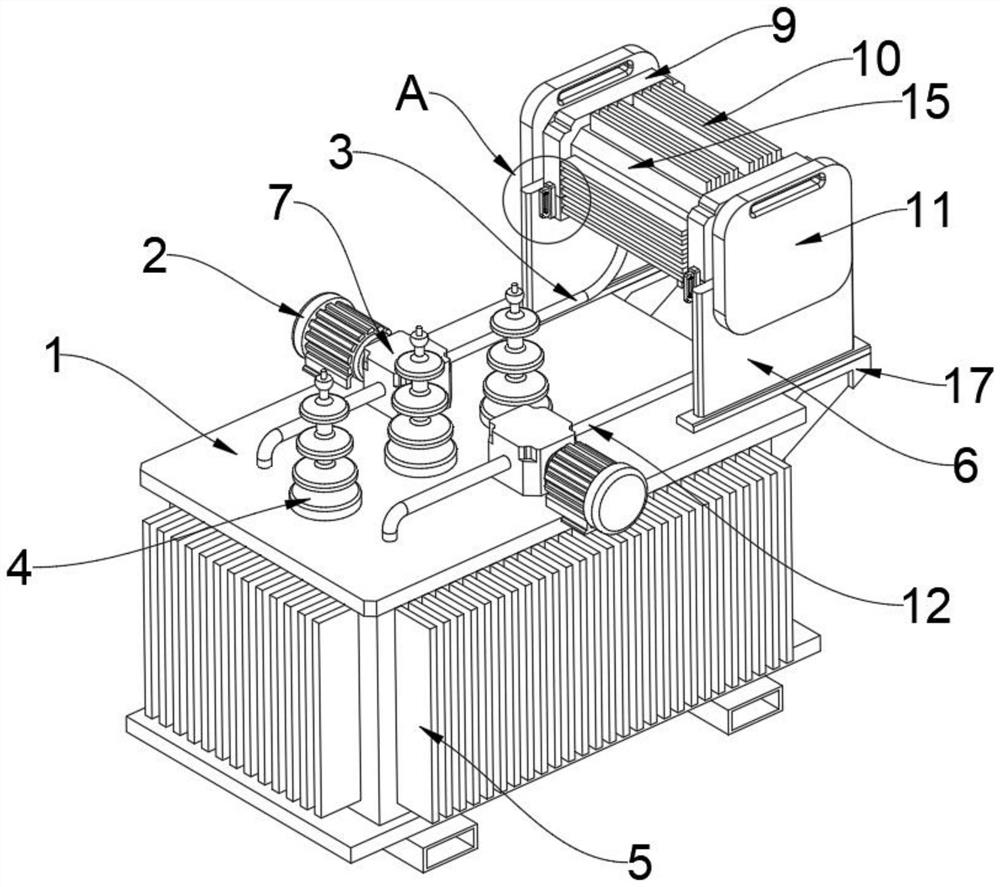
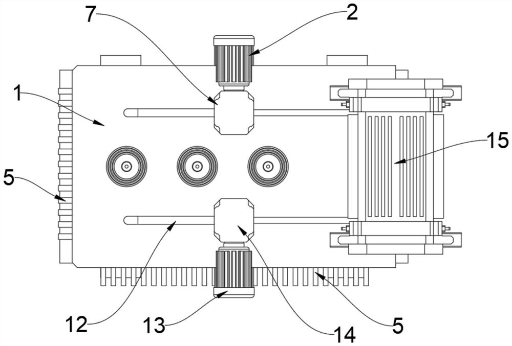
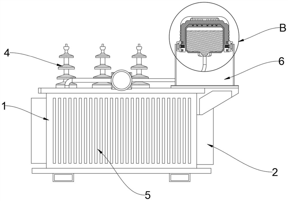
[0026] see Figure 1 to Figure 6 , an embodiment provided by the present invention: a power transformer, including a transformer housing 1, three terminals 4 are arranged in the middle of the upper end of the transformer housing 1, and cylindrical plugs are fixedly arranged on the front and back of the upper end of the transformer housing 1. Slot 17, the upper end of the cylindrical slot 17 is fixedly provided with a support plate 6, the upper ends of the two support plates 6 are clamped with a clamping plate 11, and a fuel tank barrel 15 is fixedly disposed between the two clamping plates 11, the fuel tank Both sides of the surface of the barrel 15 are fixedly provi...


PUM


Abstract

The invention discloses a power transformer, relates to the technical field of transformers, and solves the problem that cooling oil in the transformer and cooling in an oil tank barrel can only be circulated in a one-way manner and cannot be circulated in a two-way manner. A power transformer comprises a transformer shell, three binding posts are arranged in the middle of the upper end of the transformer shell, cylindrical slots are fixedly formed in the front and back of one side of the upper end of the transformer shell, supporting plates are fixedly arranged at the upper ends of the cylindrical slots, clamping plates are arranged at the upper ends of the two supporting plates in a clamped mode, and the upper ends of the clamping plates are fixedly connected with the transformer shell. An oil tank barrel is fixedly arranged between the two clamping plates, and U-shaped matching frames are fixedly arranged on the two sides of the surface of the oil tank barrel. According to the invention, the six cylindrical slots are uniformly arranged at the upper end of the oil tank barrel, so that the cylindrical pins at the lower end of the U-shaped matching frame can be inserted into the cylindrical slots, and the insertion matching type between the U-shaped matching frame and the oil tank barrel is improved.

Description

technical field [0001] The invention relates to the technical field of transformers, in particular to a power transformer. Background technique [0002] With the rapid development of social economy, transformers are the basic equipment for power transmission and distribution, and are widely used in industry, agriculture, transportation, urban communities and other fields. There are about 17 million transformers operating on the grid in my country, with a total capacity of about 11 billion kVA. Transformers are devices that use the principle of electromagnetic induction to change AC voltage. The main components are primary coils, secondary coils and iron cores. The main functions are: voltage conversion, current conversion, impedance conversion, isolation, voltage stabilization. [0003] However, the cooling oil in the existing transformer and the cooling inside the oil tank barrel can only flow in one direction, and cannot carry out two-way circulation, which makes the heat...

Claims


Application Information

Patent Timeline
IPC IPC(8): H01F27/02H01F27/14H01F27/22
CPCH01F27/14H01F27/22H01F27/025
Inventor 潘志杰邓冠军邓祁莉
Owner 广东拓杰机电工程有限公司
Why Eureka
Try Eureka