Oil-water separator

A technology of oil-water separator and water collecting chamber, which is applied in separation method, liquid separation, immiscible liquid separation and other directions, can solve the problems of poor oil-water separation effect, etc. Effect

Pending Publication Date: 2022-05-17
珠海三锐精工科技有限公司
View PDF5 Cites 1 Cited by
  • Summary
  • Abstract
  • Description
  • Claims
  • Application Information

AI Technical Summary

Problems solved by technology

However, during the continuous operation of the oil-water separation device, due to the continuous discharge of waste water into the separation tank, the surface of the separation tank generates wave fluctuations, and it is easy to make part of the water on the liquid surface follow the oil and discharge from the oil outlet, so that the separated oil contains A certain amount of water, the separated water contains a certain amount of oil, resulting in poor oil-water separation

Method used


Image

  • Oil-water separator
  • Oil-water separator
  • Oil-water separator

Examples


Embodiment Construction

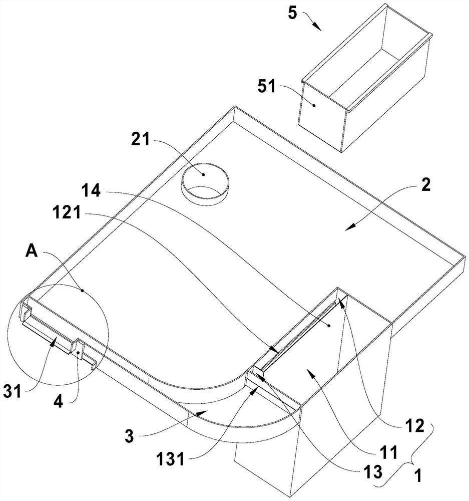
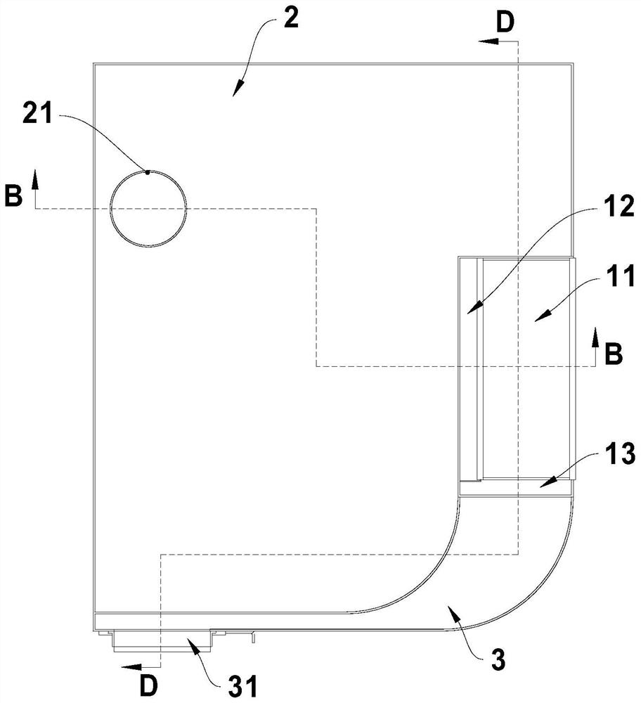
[0030] see Figure 1 to Figure 3 , The oil-water separator provided in this embodiment includes a mixing tank 1, a water collecting tank 2 and an oil collecting tank 3, and the mixing tank 1, the water collecting tank 2 and the oil collecting tank 3 are arranged in a rectangular shape to save space.

[0031] The mixing tank 1 is set as a rectangle, and the mixing tank 1 is provided with a mixing chamber 11, a water collecting chamber 12 and an oil collecting chamber 13, the area of ​​the mixing chamber 11 is larger than the area of ​​the water collecting chamber 12, and the area of ​​the mixing chamber 11 is also larger than the oil collecting chamber 13 area. The water collecting chamber 12 is arranged on one side of the mixing chamber 11 extending along the length direction of the mixing chamber 11, and the lower part of the water collecting chamber 12 communicates with the lower part of the mixing chamber 11. Oil and water separation. The oil collecting chamber 13 is arra...


PUM


Abstract

The oil-water separator comprises a mixing tank, a water collecting tank and an oil collecting tank, a mixing cavity, a water collecting cavity and an oil collecting cavity are formed in the mixing tank, the lower portion of the water collecting cavity is communicated with the lower portion of the mixing cavity, the lower portion of the oil collecting cavity is communicated with the middle or the upper portion of the mixing cavity, and an overflow opening is formed in the upper portion of the water collecting cavity. An oil overflowing opening is formed in the upper part of the oil collecting cavity and is higher than the water overflowing opening in the vertical direction; the water collecting tank is communicated with the water collecting cavity through the overflow port, a drain pipe is arranged in the water collecting tank, and a water inlet of the drain pipe is higher than the overflow port in the vertical direction; the oil collecting groove is communicated with the oil collecting cavity through the oil overflowing opening, the oil collecting groove is provided with an oil discharging opening, and the oil discharging opening is higher than the oil overflowing opening in the vertical direction. The oil-water separator has the advantages of no electric energy consumption and good oil-water separation effect.

Description

technical field [0001] The invention relates to the field of oil-water separation devices, in particular to an oil-water separator without consuming energy consumption. Background technique [0002] The industrial production process will produce a large amount of wastewater, which contains lubricating oil. The density of lubricating oil is lower than that of water, so the lubricating oil will float on the water. If the waste water is directly discharged, it will cause environmental pollution. Therefore, the factory is generally equipped with an oil removal device. The commonly used oil removal device in the factory is an oil scraper, which is also called an oil skimmer, an oil-water separator, a floating oil removal machine, etc. The oil scraper uses the specific physical characteristics between oil and water to The steel belt works continuously to absorb and remove the slick oil on the surface of the wastewater. However, the oil scraper needs to be powered on to work, and...

Claims


Application Information

Patent Timeline
Patent Type & Authority Applications(China)
IPC IPC(8): B01D17/032B01D17/02
CPCB01D17/10B01D17/0214
Inventor 陈晓奇
Owner 珠海三锐精工科技有限公司
Why Eureka
Try Eureka