
Sensor for heart blood pump and heart blood pump

A sensor and blood pump technology, used in blood pumps, suction devices, hypodermic injection devices, etc., can solve the problems of high assembly process requirements, troublesome assembly, thrombosis, etc., and achieves low assembly process requirements, small damage to human tissue, Small diameter effect

Pending Publication Date: 2022-05-17
SUZHOU HENGRUI HONGYUAN MEDICAL TECH CO LTD
View PDF1 Cites 0 Cited by
  • Summary
  • Abstract
  • Description
  • Claims
  • Application Information

AI Technical Summary

Problems solved by technology

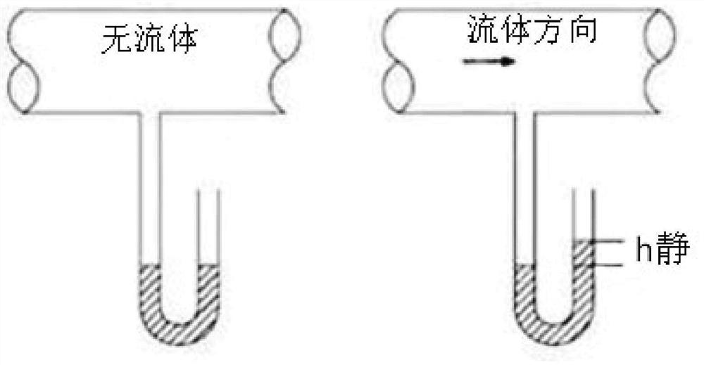
The patent (US9669142) provides a pressure sensor that is fixed on the blood pump catheter. In order to measure the blood static pressure that is not affected by the blood flow velocity, this pressure sensor needs to add additional "wall" parts around the sensing surface of the sensor. In order to create a blood stagnation area to measure the static pressure of the blood; on the one hand, this scheme has a complex structure, and on the other hand, it is easy to form a thrombus in the blood stagnation area after a long time
Moreover, the pressure sensing surface of the pressure sensor is perpendicular to the axis of the catheter, which requires high assembly technology and is troublesome to assemble.

Method used


Image

  • Sensor for heart blood pump and heart blood pump
  • Sensor for heart blood pump and heart blood pump
  • Sensor for heart blood pump and heart blood pump

Examples


Embodiment 1

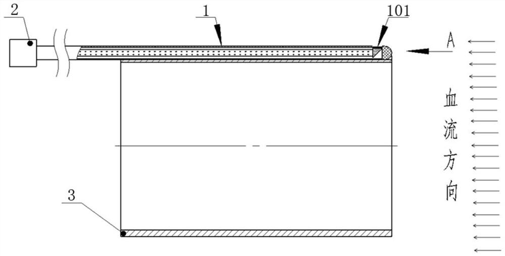
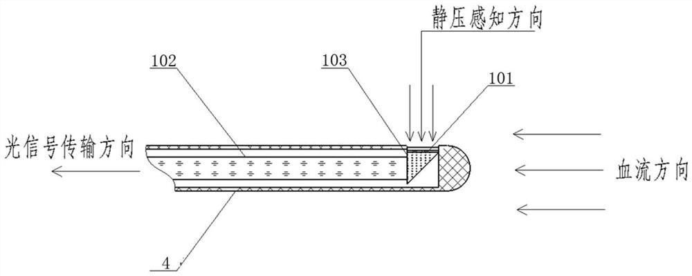
[0040] refer to Figure 2-5 In this embodiment, the sensor 1 includes a pressure-sensing membrane chip 101 and an optical signal transmission line 102, both of which are arranged parallel to the axial direction of the delivery sleeve 3; the proximal end of the optical signal transmission line 102 is connected to the background The controller 2, the far end is connected with the pressure-sensing film chip 101 through the path element, and the path element 103 is used to convert the vertical light signal (the light signal perpendicular to the direction of the pressure-sensing film chip 101) into a horizontal light signal (parallel to the light signal optical signal in the direction of transmission line 102).

[0041] In this embodiment, optical fiber is preferably used as the optical signal transmission line 102 , of course, other optical signal transmission lines with equivalent functions may also be used in other embodiments, which is not limited here.

[0042]In this embodim...

Embodiment 2

[0058] This embodiment is an adjustment made on the basis of Embodiment 1.

[0059] Specifically, refer to Figure 6-10 , in this embodiment, the sensor includes a sleeve structure 4, an optical signal transmission line 102 and a pressure sensing film chip 101 are arranged in the sleeve structure 4, the optical signal transmission line 102 is arranged along the axial direction of the sleeve structure 4, and the optical signal transmission line The end surface of the distal end of 102 has an opening, and the pressure-sensing membrane chip 101 is installed in the opening, and the pressure-sensing membrane chip 101 is perpendicular to the optical signal transmission line 102 and connected to it.

[0060] In this embodiment, the arrangement of path components is omitted, so that the pressure-sensing film chip 101 is vertically connected to the optical signal transmission line 102, and the optical signal transmission is directly realized.

[0061] In this embodiment, the sleeve st...

Embodiment 3

[0065] This embodiment provides a cardiac blood pump. At least one pressure sensor is provided on the delivery sleeve of the cardiac blood pump, and the pressure sensor adopts the sensor described in Embodiment 1 or Embodiment 2.

[0066] The cardiac blood pump is suitable for right ventricular assist devices and also for left ventricular assist devices; the left ventricle assists in detecting aortic root blood pressure, and the corresponding right ventricle assists in detecting right atrial blood pressure; the left ventricle assists in detecting left ventricular blood pressure, corresponding to right ventricle assisting detection pulmonary artery blood pressure.

[0067] Taking left ventricular assist as an example, at least one pressure sensor, preferably one pressure sensor, is installed on the heart blood pump, and the static pressure sensing end of the pressure sensor is fixed on the outer surface of the proximal sleeve of the heart blood pump to detect blood pressure at t...


PUM


Abstract

The invention provides a sensor for a heart blood pump and the heart blood pump, the sensor comprises a static pressure sensing end arranged on a heart blood pump conveying sleeve, and the static pressure sensing end is used for detecting the static pressure of blood flowing through the outer side of the conveying sleeve; the static pressure sensing end comprises a pressure sensing film chip and an optical signal transmission line, the pressure sensing film chip is provided with a pressure sensing face making contact with blood, and the pressure sensing face is parallel to the axial direction of the conveying sleeve. The pressure sensing membrane chip obtains static pressure signals in the direction perpendicular to the blood flow direction and transmits the static pressure signals out through the optical signal transmission line. According to the sensor, the pressure sensing face is parallel to the blood flowing direction, the blood static pressure is directly measured, a blood retention area does not need to be arranged at the static pressure sensing end to measure the blood static pressure, thrombus is avoided, it is guaranteed that the blood static pressure can be measured when blood flows, and the sensor can be used for short-term and long-term heart blood pump support.

Description

technical field [0001] The invention relates to the technical field of medical device design, in particular to a sensor for a heart blood pump and the heart blood pump. Background technique [0002] Heart failure refers to the failure of the systolic function and (or) diastolic function of the heart to fully discharge the venous return blood from the heart, resulting in blood stasis in the venous system and insufficient blood perfusion in the arterial system, thereby causing cardiac circulation syndrome. Current treatments for heart failure include drug therapy, heart replacement surgery, and left ventricular assist devices. Among them, the left ventricular assist device is to pump blood through the heart blood pump to promote the flow of blood in the heart. This solution has the advantages of good therapeutic effect and low cost. [0003] For the current intracardiac blood pump, in order to sense the intravascular pressure, a pressure sensor is usually used. The patent (U...

Claims


Application Information

Patent Timeline
Patent Type & Authority Applications(China)
IPC IPC(8): A61M60/165
Inventor 程小明黄霖
Owner SUZHOU HENGRUI HONGYUAN MEDICAL TECH CO LTD
Learn More