Antenna deployable assembly

An antenna and component technology, applied in the field of antenna expandable components, can solve the problems of limited number of flight configurations and applications, a large number of equipment, etc., and achieve the effect of stable structure and large aperture ratio

Pending Publication Date: 2022-05-13
AIRBUS DEFENCE & SPACE
View PDF5 Cites 0 Cited by
  • Summary
  • Abstract
  • Description
  • Claims
  • Application Information

AI Technical Summary

Problems solved by technology

However, they have some disadvantages such as the need for a large amount of equipment to keep the structure folded during launch, the high number of joints and moving components, and the very limited number of flight configurations and applications

Method used


Image

  • Antenna deployable assembly
  • Antenna deployable assembly
  • Antenna deployable assembly

Examples


Embodiment Construction

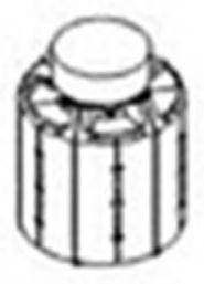
[0049] exist Figure 2A , 2B and 2C show several stages of the antenna deployable assembly of the present invention. Figure 2A shows the stowed position, Figure 2B shows the middle position where the component is expanded, Figure 2C The fully expanded position is shown.

[0050] Figures 6A to 6F Also shown are several stages of the antenna deployable assembly of the present invention, with more intermediate positions.

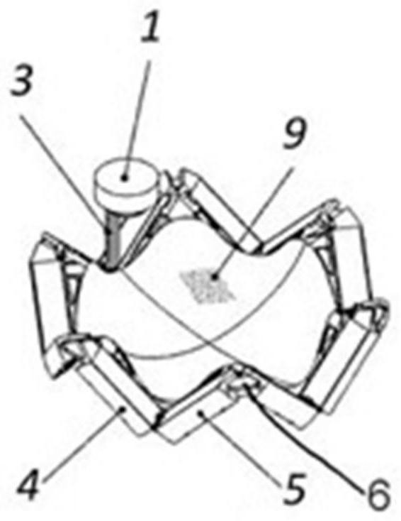
[0051] Figure 7 is a detailed view of the expandable assembly of the present invention in the middle of the deployment process, with all its elements visible.

[0052] The antenna deployable components shown in these figures include:

[0053] A structure comprising:

[0054] n pairs of segments 4, 5, each pair of segments 4, 5 corresponding to an edge of the expanded polygonal shape,

[0055] n hinge joints, between two segments 4, 5 of an edge, and

[0056] n hinged corner links 6, between every two adjacent sides, and

[0057] reflective surface...


PUM


Abstract

An antenna deployable assembly comprising: a structure comprising: n pairs of segments (4, 5), each pair of segments (4, 5) corresponding to one edge of a deployable polygonal shape, n hinge joints between two segments (4, 5) of one edge, and n hinge angle links (6) between every two adjacent edges, such that the structure can be changed from a stowed position of a substantially cylindrical shape to a deployed position of a substantially planar polygonal shape having n sides; the invention relates to a deployable assembly (1) comprising two segments (4, 5), and a reflective surface (9), said deployable assembly further comprising: a deployable boom (3) between the two segments (4, 5), said deployable boom (3) being stowed between the two segments (4, 5) prior to deployment, the deployable boom (3) terminating in a feed line (1), the feed line (1) electromagnetically feeding the antenna, and comprising a clamping element (2) for keeping the structure closed when the feed line (1) is stowed, the feeder line (1) plays a role of a structural supporting element when being folded and plays a role of an electromagnetic feeder line of the antenna when being unfolded; a set of tensor elements (8) protruding from the back of the segments (4, 5); and a cable network (7) capable of shaping the reflective surfaces (9) such that the respective cables are held by the tensor elements (8).

Description

technical field [0001] The present invention relates to a deployable assembly for antennas mainly used in space systems, and more particularly to a deployable assembly for deploying large parabolic reflectors. This component is suitable for a variety of purposes, not only for deploying large reflectors, but also for building large antennas for Earth observation and telecommunications, for building collapsible satellite constellations, and even for building space debris capture systems. Background technique [0002] A number of deployable reflector antenna structures are known in the art. [0003] US 4030102 A, relating to "Deployable reflector structures", discloses a support structure which unfolds like a spoked wheel and is retractable into a compact volume by folding the rim and coilable spokes, which is an efficient Stable structures for storing, deploying and supporting surfaces (such as radar and communication antennas, shielding, earth exploration, solar arrays and s...

Claims


Application Information

Patent Timeline
Patent Type & Authority Applications(China)
IPC IPC(8): H01Q1/08H01Q1/12H01Q15/16H01Q1/28
CPCH01Q1/288H01Q1/08H01Q15/161H01Q1/1235
Inventor J·L·普拉萨莫拉F·J·塞斯佩多萨卡斯坦
Owner AIRBUS DEFENCE & SPACE
Why Eureka
Try Eureka