Lubricating oil supply device for stepless speed changer

A technology of continuously variable transmission and transmission, which is applied in the direction of lubricating pumps, transmission devices, friction transmission devices, etc., and can solve problems such as increased protrusion

Inactive Publication Date: 2004-04-07
HONDA MOTOR CO LTD
View PDF2 Cites 1 Cited by
  • Summary
  • Abstract
  • Description
  • Claims
  • Application Information

AI Technical Summary

Problems solved by technology

However, the extension of the transmission shaft from the above-mentioned wall portion becomes larger, leading to an increase in the size of the power transmission including the continuously variable transmission.

Method used


Image

  • Lubricating oil supply device for stepless speed changer
  • Lubricating oil supply device for stepless speed changer
  • Lubricating oil supply device for stepless speed changer

Examples


Embodiment Construction

[0017] Hereinafter, an embodiment of the present invention will be described based on an embodiment of the present invention shown in the drawings.

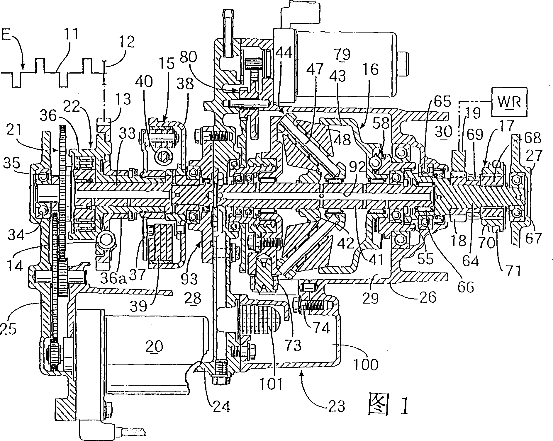
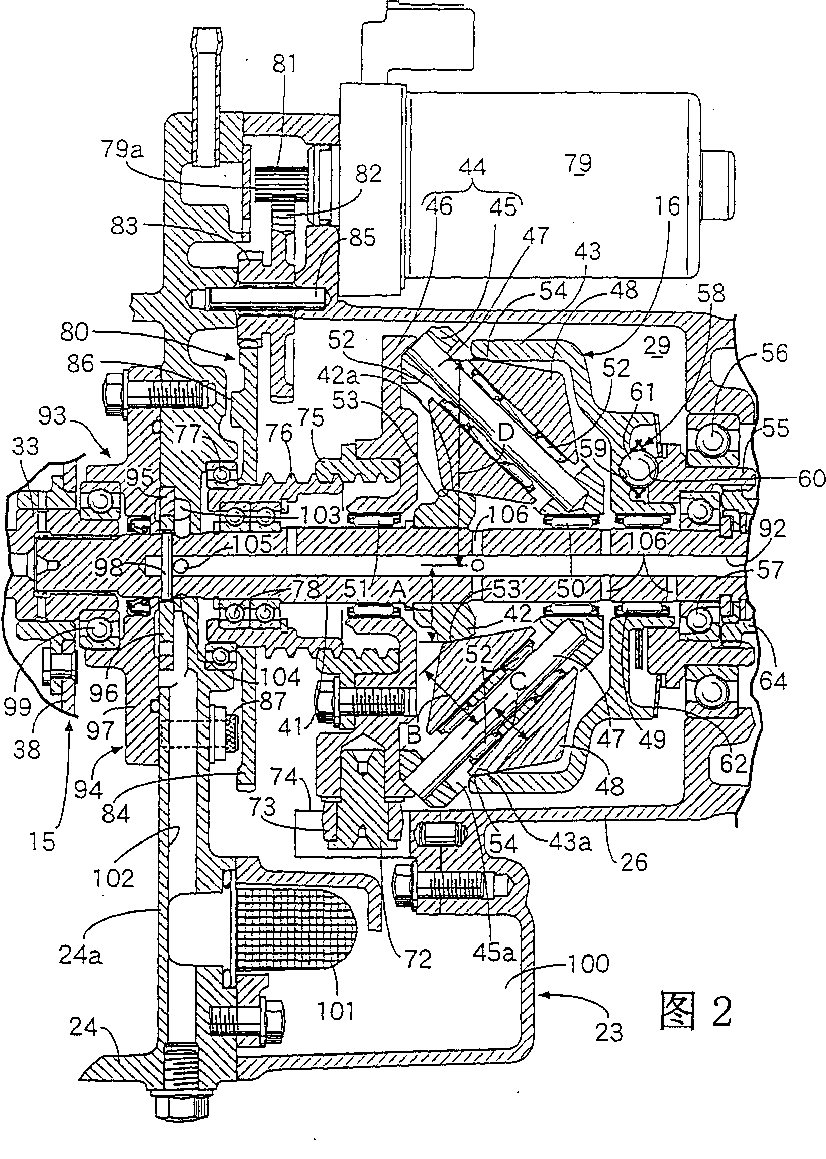
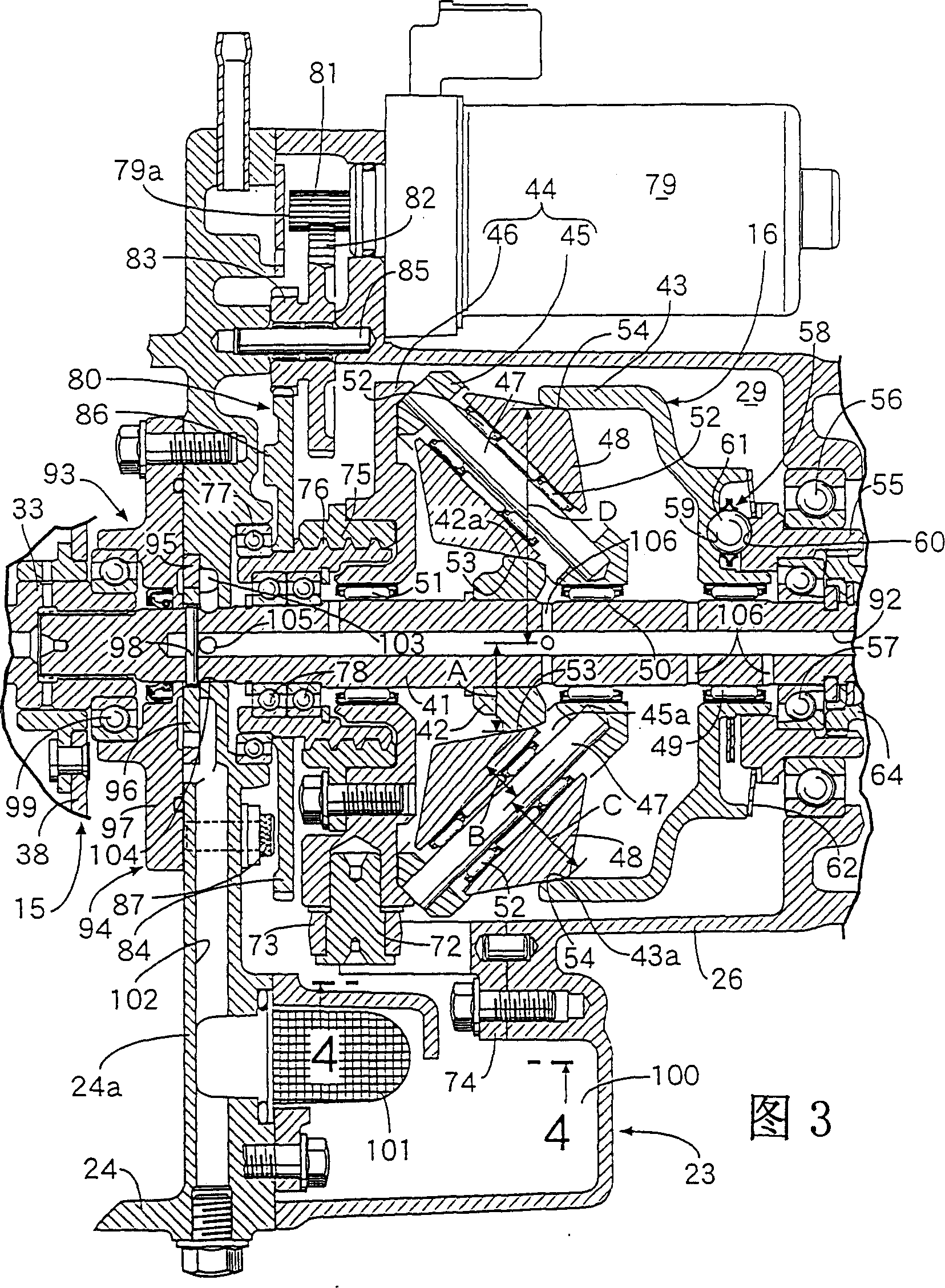
[0018] Figure 1 to Figure 5 One embodiment of the present invention is shown, and FIG. 1 is a longitudinal sectional view showing a power transmission mechanism between an engine and a continuously variable transmission. Fig. 2 is an enlarged longitudinal sectional view of the continuously variable transmission in a low gear ratio state. Fig. 3 is an enlarged longitudinal sectional view of the continuously variable transmission in a high gear ratio state. Figure 4 It is a view from the direction of 4-4 in FIG. 3 . Figure 5 It is a cross-sectional view showing the connection structure between the bracket and the potentiometer.

[0019] First, in FIG. 1, the output of an engine E mounted on a vehicle such as a motorcycle passes through a transmission gear 12, a driven gear 13, a buffer spring 14, an automatic centrifugal clutc...


PUM


Abstract

A lubricating oil supply system for an infinitely variable transmission wherein the infinitely variable transmission has a transmission shaft provided with a lubricating oil path and is rotatably mounted through the wall section of a casing. The infinitely variable transmission is housed in a transmission case partly defined by the wall section. An input rotary member is provided that is relatively unrotatably connected to the transmission shaft on the outside of the transmission case. An oil pump is provided for supplying lubricating oil to the lubricating oil path. The oil pump is located in the casing. In this infinitely variable transmission, the oil passage from the oil pump to the lubricated portion of the infinitely variable transmission is simplified in structure and the oil passage is substantially reduced in length, thereby enabling a decrease in the length of the transmission shaft.

Description

technical field [0001] The present invention relates to an improvement of a lubricating oil supply device for a continuously variable transmission, which has a transmission shaft that can freely rotate through a wall portion provided on a casing, is freely rotatably supported on the casing, and is provided with a lubricating oil passage The continuously variable transmission is accommodated in a transmission chamber defined by the above-mentioned wall part and formed on the above-mentioned case. Outside the above-mentioned transmission chamber, an input rotating member is connected to the transmission shaft in a non-rotatable manner on the case. Equipped with an oil pump that supplies lubricating oil to the aforementioned lubricating oil passage. Background technique [0002] Conventionally, such lubricating oil supply devices have been known in the art, for example, Japanese Patent Application Laid-Open No. 11-79054 and Japanese Patent Laid-Open No. 11-270641 disclose such ...

Claims


Application Information

Patent Timeline
IPC IPC(8): F16H15/52F16H15/20F16H57/04F16H61/664F16N7/38F16N13/20
CPCF16H57/0487F16H61/664F16H57/0434F16H15/20F16H57/0402Y10T74/2186
Inventor 冢田善昭黑木正宏
Owner HONDA MOTOR CO LTD
Why Eureka
Try Eureka